Coupled-inductor based resonator and formed voltage controlled oscillator thereof
a voltage control and oscillator technology, applied in the field of voltage control oscillators, can solve the problems of increasing cost and complexity, negative impact on reliability and robustness, etc., and achieve the effects of reducing voltage swing, and reducing cost and complexity
- Summary
- Abstract
- Description
- Claims
- Application Information
AI Technical Summary
Benefits of technology
Problems solved by technology
Method used
Image
Examples
embodiment 1
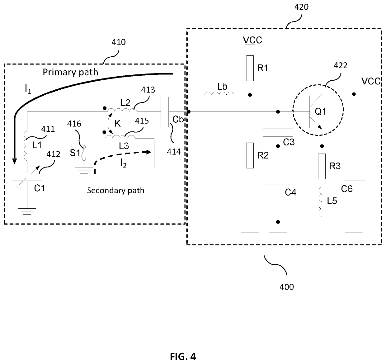
[0029]FIG. 4 is a circuit diagram of a multi-band VCO according to embodiment 1 of the invention. As shown in FIG. 4, the multi-band VCO 400 comprises a resonator 410 and a negative resistance circuit 420. The resonator 410 is a coupled-inductor based resonator comprising a primary path and a secondary path inductively coupled to the primary path. The resonator 410 incorporates a first LC tuning stage (comprising inductor L1 411 and capacitor C1 412), a coupled-inductor tuning stage (comprising inductor L2 413 and the secondary path) and a capacitor Cb 414 for DC or low frequency isolation. The coupled-inductor tuning stage inductively couples to the secondary path. The secondary path comprises a controllable switch S1 416 and a secondary inductor L3 415 inductively coupled to inductor L2 413 in the primary path. The controllable switch S1 416 may be controlled to switch ON or OFF to engage / disengage the inductive coupling between inductor L2 on the primary path and inductor L3 on t...
embodiment 2
[0037]FIG. 5 is a circuit diagram of a VCO 500 with multiple switches in secondary path according to embodiment 2 of the invention. Similar to the VCO 400 shown in FIG. 4, the VCO 500 also comprises a coupled-inductor based resonator 510 comprising a primary path and a secondary path inductively coupled to the primary path. Different from the primary path in resonator 410, the primary path in resonator 510 comprises multiple LC tuning stages coupled in series, e.g. a first LC tuning stage 512 comprising a first inductor L1 and a first capacitor C1, a second LC tuning stage 514 comprising a second inductor L3 and a second capacitor C2. The inductor of each LC tuning stage is inductively coupled to a respective secondary inductor in the secondary path. For example, the first inductor L1 inductively couples to a first secondary inductor L2 and the second inductor L3 inductively couples to a second secondary inductor L4. Capacitors C1 and C2 may be one or more fixed capacitor, one or mo...
embodiment 3
[0042]In some embodiments, the multi-band VCO may be configured as a push-push VCO to further reduce oscillator phase noise as compared to conventional VCO. FIG. 6 is a multi-band push-push VCO 600 according to embodiment 3 of the invention. The push-push VCO 600 is formed by having two single-ended VCO 610 and 620 implemented in a balanced structure. The single-ended VCOs 610 and 620 couple in a balanced structure symmetrically along a symmetric line 660, which may be a virtual ground. The output signal from location 630 of the push-push VCO is fed to a single-ended buffer amplifier A1640 via a capacitor Cd 632 to generate an amplified output signal 642. Due to the push-push VCO structure, output signal from location 630 (or from other points along virtual GND, e.g., connection point between C1 and C1′) naturally cancel odd harmonics and amplify even harmonics, output location 630 is naturally a good location to tap output an output signal with doubled signal frequency of resonance...
PUM
 Abstract
Description
Claims
Application Information
 - R&D
- Intellectual Property
- Life Sciences
- Materials
- Tech Scout
- Unparalleled Data Quality
- Higher Quality Content
- 60% Fewer Hallucinations
Browse by: Latest US Patents, China's latest patents, Technical Efficacy Thesaurus, Application Domain, Technology Topic, Popular Technical Reports.
© 2025 PatSnap. All rights reserved.Legal|Privacy policy|Modern Slavery Act Transparency Statement|Sitemap|About US| Contact US: help@patsnap.com


