Apparatus and methods utilizing emissive patterns to determine positional information

a position information and emissive pattern technology, applied in the field of apparatus and methods for determining position information, can solve the problems of backlash in the drive mechanism, deviations from the expected thread-to-thread location of screw-type drives and teeth, and more expensive linear encoders, so as to improve the accuracy and improve the accuracy of position information , the effect of superior positional resolution

Active Publication Date: 2020-12-22
MOYER THOMAS P
View PDF45 Cites 0 Cited by
  • Summary
  • Abstract
  • Description
  • Claims
  • Application Information

AI Technical Summary

Benefits of technology

[0017]Advantageously, embodiments in accordance with aspects of the invention may provide apparatus and methods that offer one or more of: (a) greater positional resolution at similar cost to conventional position encoding techniques, or even superior positional resolution at lower cost; (b) operationally acceptable determination speeds; (c) positional information at, or closer to, an end effector where conventional positional error typically increases; and (d) automation that eliminates error introduced by human operators. Applications for aspects of the invention include, as just a few non-limiting examples: autonomously piloted vehicles, multi-axis robotic arms, 3D printers, CNC machine tools, and cranes.

Problems solved by technology

Machines with higher resolution requirements will often afford the more expensive linear encoders.
Backlash in the drive mechanism, and deviations from expected thread-to-thread locations in screw-type drives and tooth-to-tooth positions in rack-and-pinion systems are unaccountable positional errors in the rotary encoder systems.
In both types of encoder systems, deflection of the axes, play in the connections between axes, and thermal expansion around uncontrolled locations also exist as unaccountable positional errors.
Nevertheless, the absence of any such member spanning the fixed-to-movable machine portions precludes the use of such linear encoders.
This combination suffers from having the long elastic length of the wire rope between the measuring location and the end effector.
Such operators have historically had high maintenance requirements, frequent downtimes, and long lead times before achieving the required skill levels.
Nevertheless, these solutions, too, are frequently unsatisfying.
Compliance with the unidirectional travel requirement can be met when calibration jigging is able to provide a rigid pathway over which the reflector can be transported but is difficult to achieve in the everyday work condition of an airgap between the light source and the measured tool end effector.
This difficulty is further exacerbated in machines in which the working distance over which position determination is desired extends beyond a few meters.
A compounding difficulty is that the reflector source to end effector transport needs to occur after every light source power-on cycle, and after every intermittent beam occluding incident such as an operator or a bird moving in front of the beam.
These startup and maintenance difficulties for this inherently incremental-only technique, have caused commercial energy beam-based distance measurements to accept lower resolution by implementing depth measurements based on time-of-flight for most non-calibration, day-to-day position measurement operations.
Systems based on other phenomena each have unique detriments which are correlated with their not having found widespread commercial application.
Radio wave interferometry has a combination of undesirably long wavelength compared to light, and has additional health concerns about freely-emitted electromagnetic radiation.
Moire interferometric systems suffer from the high expense and limited movement distances which arise from the precision positioning requirements for both the moire grids and the illuminating source.
Sound-based systems, of both the interferometric and time-of-flight distance measurement types suffer from imprecision due to changes in the propagation speed of sound due to air temperature and humidity effects.
Auditory volume and ambient sound interference considerations also limit their effective range to a few dozen meters.
The long wavelength of sound waves also contributes to limited resolution for these systems.
Here too, however, they do express the same undesirable azimuth and inclination resolution limitations as the interferometric systems.
In addition, the high speed of light imposes a unique and heavy cost burden on such systems.
As such, cost is the primary detriment of such systems.
Nevertheless, each of these attempts suffers from one or more of the following disadvantages: (a) poor positional resolution; (b) limited ability to handle larger dimensions; (c) the need for prohibitively expensive equipment such as extremely high-resolution cameras; (d) high computational overhead resulting in slow response; and (e) being characterized by resolution that decreases as measured dimensions increase.

Method used


Image

  • Apparatus and methods utilizing emissive patterns to determine positional information
  • Apparatus and methods utilizing emissive patterns to determine positional information
  • Apparatus and methods utilizing emissive patterns to determine positional information

Examples


Embodiment Construction

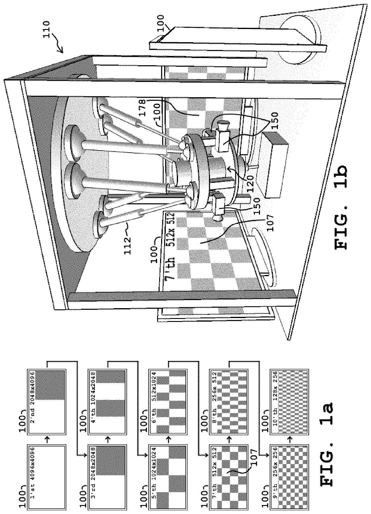
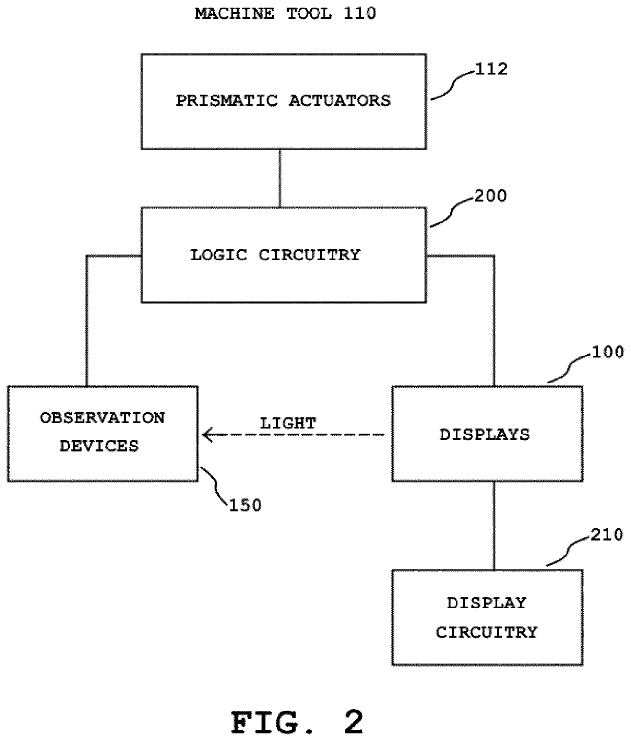
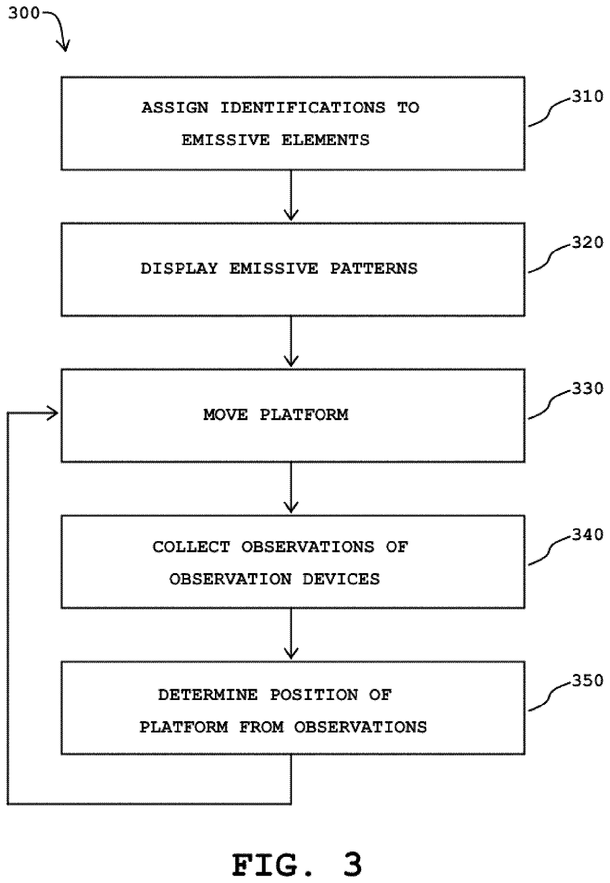
[0036]The present invention will be described with reference to illustrative embodiments. For this reason, numerous modifications can be made to these embodiments and the results will still come within the scope of the invention. No limitations with respect to the specific embodiments described herein are intended or should be inferred.

[0037]The current invention uses one or more observation devices to mark distinguishable states of selected emissive entities as sequential control is expressed over a display such that after a fixed number of patterns have been expressed, the sequence of distinguishable states for every emissive element will have been unique. The identity of the emitters selected for observation is thereby known. Embodiments require the geometry of the observation devices to be known, and the positions of each of the emissive entities to be known relative to the other elements of the display, and the positional relationship between the observation devices and the dis...


PUM


Abstract

Absolute, non-juxtaposed position encoders (i.e., position-determining systems) for up to six degrees-of-freedom are described. Each of these apparatus includes a display, an observation device, display circuitry, and logic circuitry. The display includes a plurality of pixels. In addition, the observation device is capable of observing light emitted from a region of the display. The display circuitry is able to cause one or more emissive patterns to be displayed on the display. The logic circuitry is able to determine a position of the observation device relative to the display at least in part from the light observed by the observation device. The observation device is capable of being moved in relation to the display, or vice versa. Aspects of the invention are suitable for use in a diverse set of applications such as: autonomously-piloted vehicles, multi-axis robotic arms, three-dimensional (3D) printers, computer-numerical-control (CNC) machine tools, and cranes.

Description

FIELD OF THE INVENTION[0001]The present invention relates generally to apparatus and methods for determining positional information, and, more particularly, to apparatus and methods that use emissive patterns to determine the positions of movable objects.BACKGROUND OF THE INVENTION[0002]The gathering of positional information is important to diverse families of machines, which have a wide range of commercial functions. Computer numerical control (CNC) machines remove material to create useful shapes in metal, wood, and plastics. Material is also removed by electrical discharge machining (EDM), plasma cutting, and water jet cutting tools. Alternatively, material modification can also be additive, as in three-dimensional (3D) printing, painting, and welding. Robotic multistage articulated arms employ all of the aforementioned end effectors as well as frequently having pick-and-place grippers. Cranes lift loads and place them at desired locations, often with the position determination ...

Claims


Application Information

Patent Timeline
Patent Type & Authority Patents(United States)
IPC IPC(8): G06F3/147G01D5/26
CPCG01D5/262G06F3/147G01D5/34792G01D2205/95
Inventor MOYER, THOMAS P.
Owner MOYER THOMAS P
Why Eureka
Try Eureka