
Hydraulic seal arrangement

a technology of hydraulic seals and sealing fluids, applied in the direction of engine seals, machines/engines, mechanical equipment, etc., can solve the problems of affecting the operability and design of further system components, limiting the pressure differential that can be sustained by a traditional hydraulic seal of given dimensions, and compromising the design intent to some degree, so as to increase the swirl effect, increase the tangential velocity of the sealing fluid entering the sealing fluid zone, and increase the volume of fluid

Active Publication Date: 2021-01-05
ROLLS ROYCE PLC
View PDF10 Cites 0 Cited by
  • Summary
  • Abstract
  • Description
  • Claims
  • Application Information

AI Technical Summary

Benefits of technology

The hydraulic seal arrangement described in the patent reduces the time required to form the seal during start-up, resulting in reduced seal leakage during start-up compared to traditional hydraulic seals. The arrangement allows for quicker formation of the seal by delivering the sealing liquid in a highly swirled state, resulting in increased pressure capacity compared to traditional seals. The arrangement also provides a method for varying the seal pressure differential according to a preferred or operational model value, allowing for active control of the seal pressure. This allows for precise control of the leakage past the seal in a system with a constant rotational speed. The delivery of fluid to the seal may be remotely controlled. Overall, the hydraulic seal arrangement described in the patent improves the efficiency and control of sealing in various applications.

Problems solved by technology

In some restrictive cases, where the seal leakage flow may be, for example combustible or toxic, a zero-leakage seal may be required.
Therein, the centrifugal force imparted to the rotating sealing fluid is not in excess of the forces required to overcome the effects of gravity and the respective pressure differential and an effective seal cannot be maintained.
In applications where zero / minimal seal leakage is a design requirement, the design intent would be compromised to some degree by a traditional hydraulic seal.
In addition, there is a limit to the pressure differential that can be sustained by a traditional hydraulic seal of given dimensions, operating at a given rotational speed.
In order to accommodate larger pressure differentials, designers face the choice of increasing the dimensions of the seal, adding weight and / or cost, or operating the seal at a higher rotational speed, which adds complexity and impacts on the operability and design of further system components.
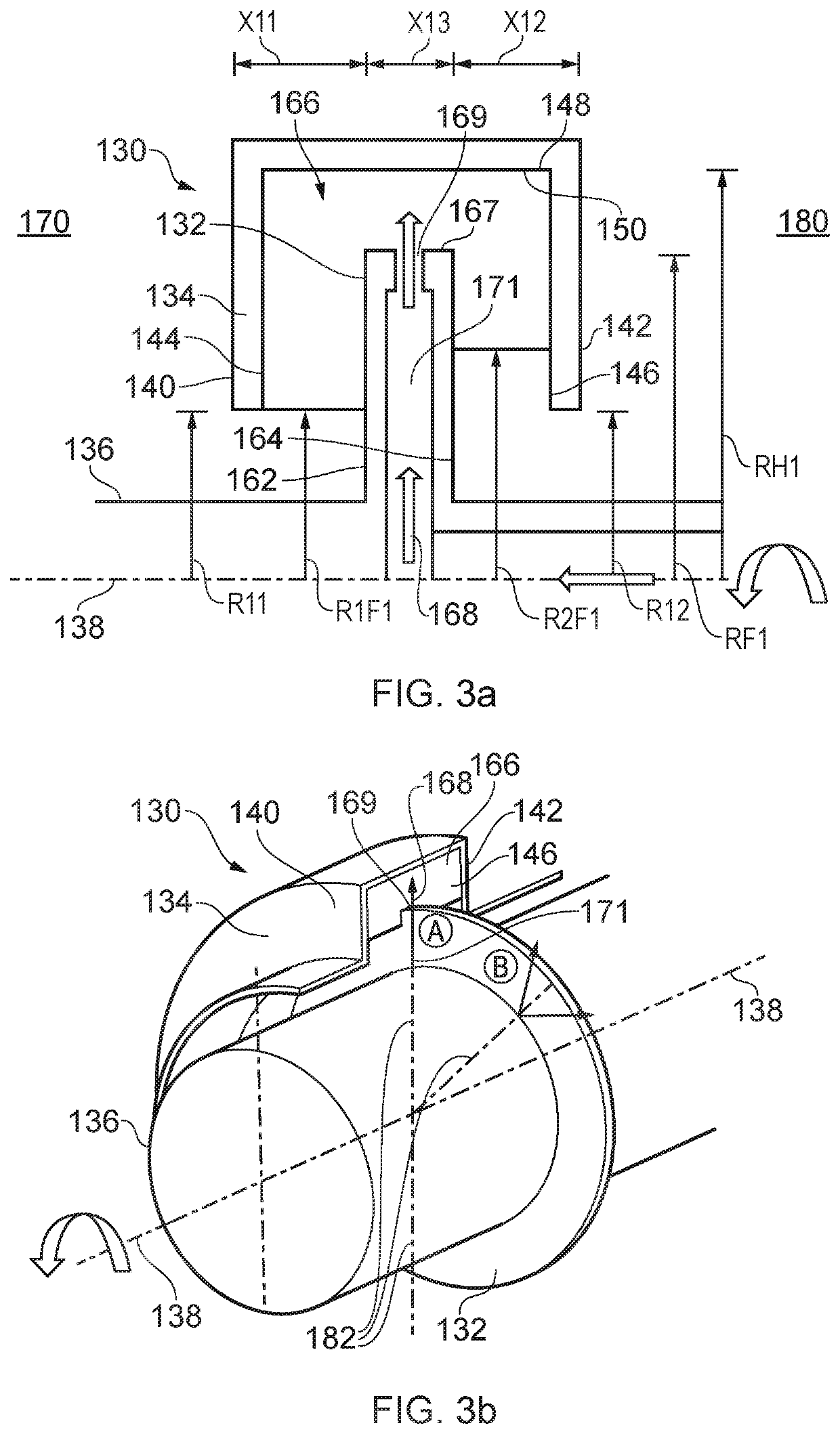
The delivery of a sealing fluid into the hydraulic seal via a linear high-pressure jet results in windage, as the sealing fluid enters the seal with little or no swirl velocity component.
This presents a number of detrimental effects to the overall efficiency of the rotating machine, notably including that the additional windage detracts from overall machine efficiency, increasing running costs.
Furthermore, the work done on the sealing fluid increases the temperature of the fluid, potentially reducing its useful life.
In the application of hydraulic seals within for example, gas turbine engines and other prime mover applications, the high-pressure delivery of sealing fluid into the hydraulic seal contributes to parasitic losses that erode thermal performance of the engine.
Furthermore, in applications where the seal fin and seal housing rotate in opposite directions the bulk rotation within the seal is low.
Such rapid formation of the seal may result in reduced seal leakage during start up over traditional hydraulic seals.

Method used


Image

  • Hydraulic seal arrangement
  • Hydraulic seal arrangement
  • Hydraulic seal arrangement

Examples


Embodiment Construction

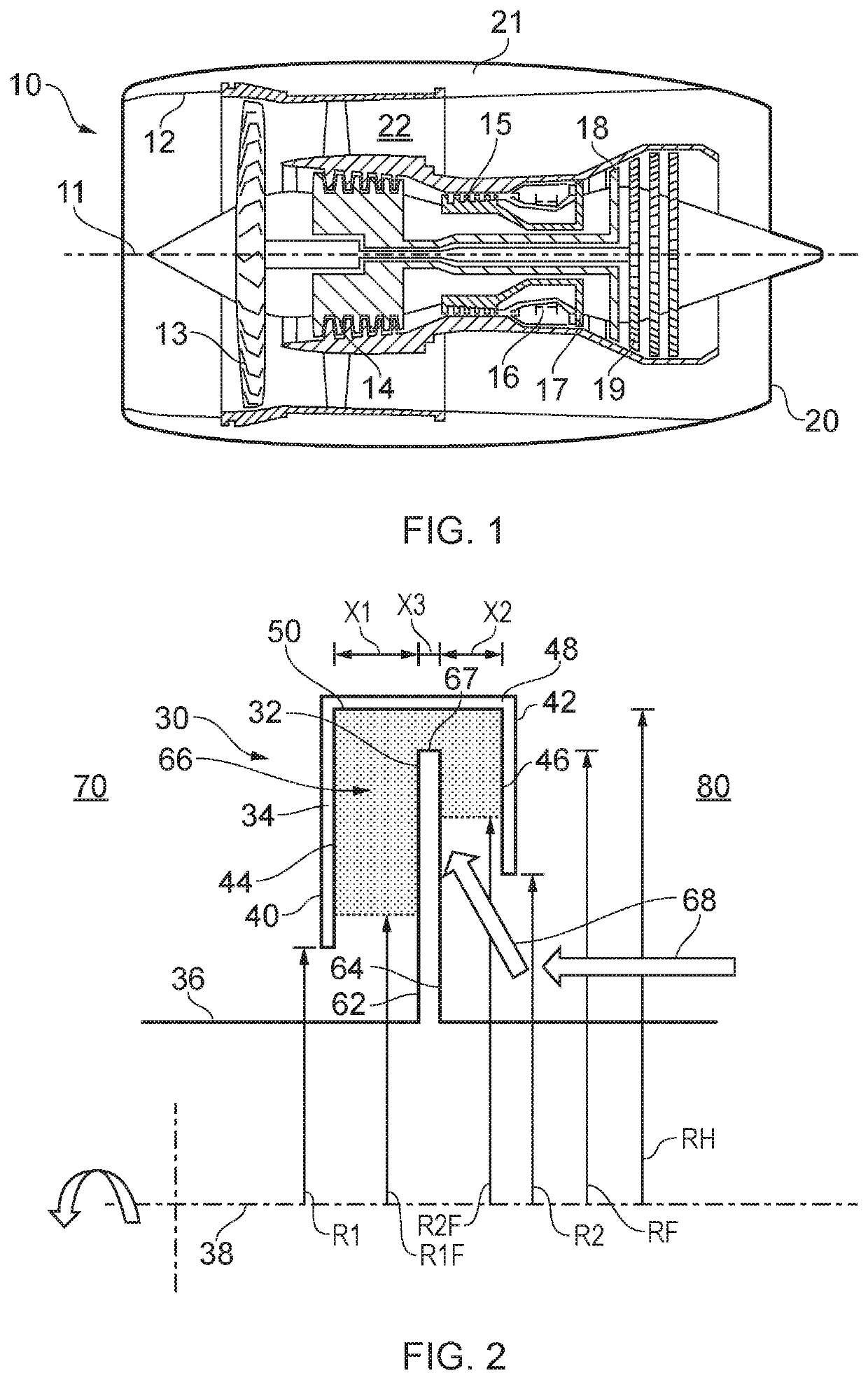
[0040]With reference to FIG. 1, a gas turbine engine is generally indicated at 10, having a principal and rotational axis 11. The engine 10 comprises, in axial flow series, an air intake 12, a propulsive fan 13, an intermediate pressure compressor 14, a high-pressure compressor 15, combustion equipment 16, a high-pressure turbine 17, an intermediate pressure turbine 18, a low-pressure turbine 19 and an exhaust nozzle 20. A nacelle 21 generally surrounds the engine 10 and defines both the intake 12 and the exhaust nozzle 20.

[0041]The gas turbine engine 10 works in the conventional manner so that air entering the intake 12 is accelerated by the fan 13 to produce two air flows: a first air flow into the intermediate pressure compressor 14 and a second air flow which passes through a bypass duct 22 to provide propulsive thrust. The intermediate pressure compressor 14 compresses the air flow directed into it before delivering that air to the high pressure compressor 15 where further comp...


PUM


Abstract

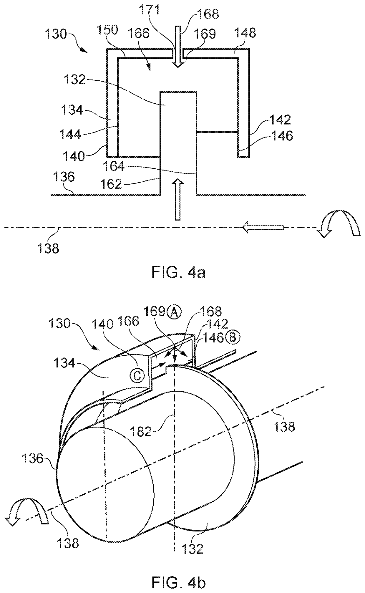
A hydraulic seal arrangement for a rotating machine comprises an annular housing disposed around a shaft having an axis of rotation, the annular housing being relatively rotatable with respect to the shaft and having a sealing fluid zone within a radially outer portion of an interior of the annular housing. A fin extends radially from the shaft into the annular housing, with at least a portion of the fin extending radially into the sealing fluid zone. In use, the sealing fluid is centrifugally accelerated before being directly introduced into the sealing fluid zone by a sealing fluid inlet so as to generate a swirl component upon its introduction.

Description

CROSS-REFERENCE TO RELATED APPLICATIONS[0001]This specification is based upon and claims the benefit of priority from UK Patent Application Number GB1717431.9 filed on Oct. 24, 2017, the entire contents of which are incorporated herein by reference.BACKGROUNDField of the Disclosure[0002]The present disclosure concerns a hydraulic seal arrangement. In particular, the present disclosure concerns a hydraulic seal arrangement for use in a rotating machine such as, for example, a gas turbine engine.Description of the Related Art[0003]In high-performance rotating machinery such as, for example, gas turbine engines, there is a requirement to achieve a seal in order to prevent the flow of a gas from a high-pressure source to a low-pressure sink. In some instances a degree of seal leakage may be tolerable and in such cases a labyrinth seal may provide an adequate solution. In some restrictive cases, where the seal leakage flow may be, for example combustible or toxic, a zero-leakage seal may...

Claims


Application Information

Patent Timeline
Patent Type & Authority Patents(United States)
IPC IPC(8): F16J15/42F01D25/18
CPCF16J15/42F01D25/183F05D2240/60
Inventor YOUNG, COLIN
Owner ROLLS ROYCE PLC
Learn More