Blocking plate structure for improved acoustic transmission efficiency

a technology of acoustic transmission and block plate, which is applied in the direction of positive displacement liquid engine, mechanical vibration separation, instruments, etc., can solve the problems of limiting the amount of acoustic energy emitted by the transducer, limiting the usability of applications that require a very thin or compact solution, and poor transmission of energy into the acoustic medium. to achieve the effect of increasing the transmission efficiency of the acoustic transducer

Active Publication Date: 2021-02-02
ULTRAHAPTICS IP LTD
View PDF171 Cites 19 Cited by
  • Summary
  • Abstract
  • Description
  • Claims
  • Application Information

AI Technical Summary

Benefits of technology

[0007]This application describes an acoustic matching structure used to increase the transmission efficiency of an acoustic transducer when emitting into a medium that has an acoustic impedance significantly lower than that of the transducer.
[0009]Specifically, an acoustic matching structure is used to increase the power radiated from a transducing element with a higher impedance into a surrounding acoustic medium with a lower acoustic impedance.

Problems solved by technology

This large impedance mismatch leads to poor transmission of energy into the acoustic medium, limiting the amount of acoustic energy emitted by the transducer.
This limits their usability for applications that require a very thin or compact solution.
A further disadvantage of conventional impedance matching layers is that the low acoustic impedance materials used may require complex manufacturing processes.
This results in decreased efficiency and output.
Although this resonant bending actuator has a much lower acoustic impedance than the bulk materials from which it is constructed (PZT and aluminum), there remains a substantial difference between the actuator impedance and air impedance, decreasing efficiency and acoustic output.
It can be seen that there will only be a limited selection of suitable materials, and for some ranges of frequencies this limited selection may be small.
But in general, suitable materials do not occur naturally.
They must be often constructed with special manufacturing processes that tend to be complex and difficult to control, leading to variable acoustic properties and variable performance as a matching layer.
An ideal matching layer for a typical resonant piezoelectric bending actuator would have even lower acoustic impedance and would be more challenging to construct.
A further problematic issue with low-density, low-speed-of-sound matching layers of suitable materials is the constraint on thickness imposed by the quarter wavelength requirement.
Therefore, assuming the material has a similar speed of sound to that of air—which would itself be difficult to achieve as it would require a high-density but low-stiffness material which would again likely require a specialist process to create—an ideal matching layer would have a thickness close to 2.14 mm.
In thickness-constrained applications, this may be too great to be viable, either commercially or for the particular application of interest.
In practice, this analytical description is not fully accurate, and the boundary condition will be mixed (neither zero pressure nor zero displacement) due to the presence of apertures near r=acavity.
The presence of apertures causes a mixed boundary condition, and this complicates the solution.
Furthermore, losses and energy propagation from the transducing element to the external acoustic medium lead to a travelling wave component in the acoustic wave.
Significantly smaller than this value will result in energy being lost to heat through thermo-viscous boundary layer effects at the walls.
The exact shape and placement of the apertures does not lend itself to closed-form analytic analysis.
Too small, however, and not enough acoustic pressure will escape per cycle therefore reducing the efficacy of the cavity as a matching layer.
Moving too far from these requirements may cause a jump in the resonant mode excited and thus deleteriously affect the efficiency obtained from the addition of the tuned structure as described previously in this document.
There is no aperture positioned along axis B as pressure radiated from an aperture at this position would be out of phase with the pressure radiated from apertures 1830 and 1860, which would cause destructive interference and lower the transducer's total pressure output.
It is unintuitive that adding a blocking plate can improve acoustic output, given that a large fraction of the propagation area of the transducing element is blocked by the plate itself.
In addition, conventional impedance matching layers require complex manufacturing processes to produce the low acoustic impedance materials, whereas the novel acoustic structure described herein can be manufactured using conventional processes e.g. machining, injection molding, etching.
Furthermore, low acoustic impedance materials typically lack robustness, whereas the required structure to implement this invention can be fabricated out of more rigid and robust engineering materials such as aluminum.
This may be limiting at high frequencies (»80 kHz), where the spacing of the thin film from the transducing element requires tight tolerances that are not reasonably achievable.
Moreover, thin polymer films lack robustness, whereas the blocking plate with its supporting structure can be fabricated out of a single piece of a more rigid and robust engineering materials such as aluminum.
This requires a substantially sub-wavelength transducing element, which limits the power output and constrains what transducing elements can be used with this matching concept.

Method used


Image

  • Blocking plate structure for improved acoustic transmission efficiency
  • Blocking plate structure for improved acoustic transmission efficiency
  • Blocking plate structure for improved acoustic transmission efficiency

Examples


Embodiment Construction

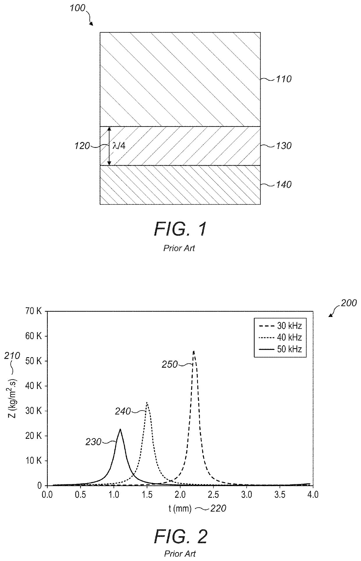
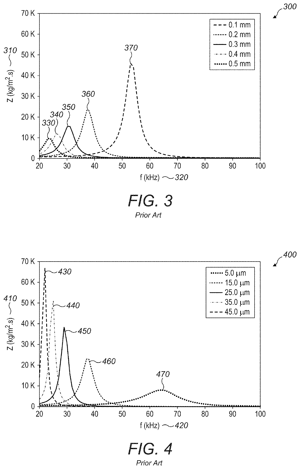
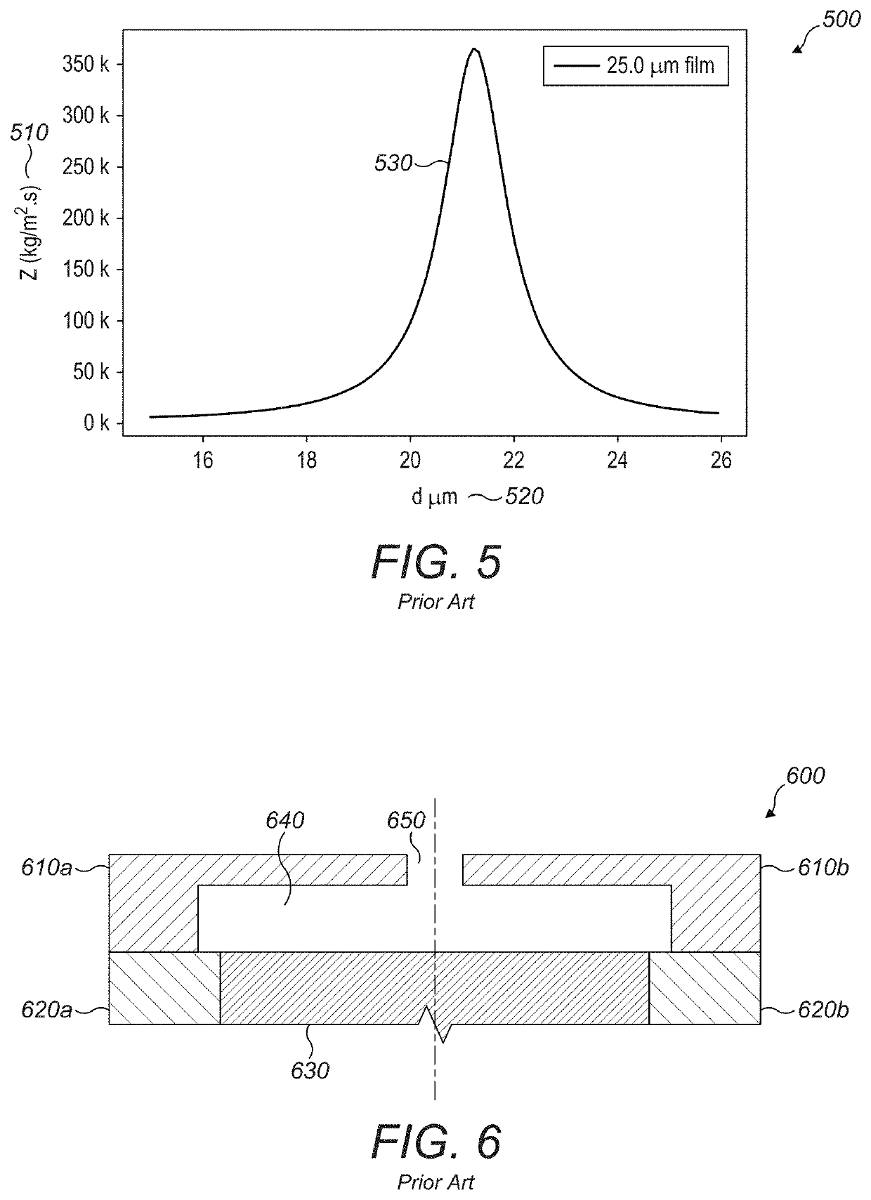
I. Acoustic Matching Layers

[0040]In this description, a transducing element directly refers to the portion of the structure that converts energy to acoustic energy. An actuator refers to the portion of the solid structure that contains the kinetic energy before transferring it to the medium.

[0041]The specific acoustic impedance of a gas or material is defined as the ratio of the acoustic pressure and the particle speed associated with that pressure, or

[0042]z=pu

[0043]This holds for arbitrary acoustic fields. To simplify this discussion, it is most useful to consider the plane wave solution to the above. This reduces the equation to scalar quantities,

z=ρc,

for a wave propagating in the same direction as the particle velocity, and where ρ is the density and c is the speed of sound of the medium. The importance of this quantity is highlighted when considering the reflection and transmission from an interface between two acoustic media with differing acoustic impedance. When a plane wav...


PUM


Abstract

An acoustic matching structure is used to increase the power radiated from a transducing element with a higher impedance into a surrounding acoustic medium with a lower acoustic impedance. The acoustic matching structure consists of a thin, substantially planar cavity bounded by a two end walls and a side wall. The end walls of the cavity are formed by a blocking plate wall and a transducing element wall separated by a short distance (less than one quarter of the wavelength of acoustic waves in the surrounding medium at the operating frequency). The end walls and side wall bound a cavity with diameter approximately equal to half of the wavelength of acoustic waves in the surrounding medium. In operation, a transducing element generates acoustic oscillations in the fluid in the cavity. The transducing element may be an actuator which generates motion of an end wall in a direction perpendicular to the plane of the cavity to excite acoustic oscillations in the fluid in the cavity, and the cavity geometry and resonant amplification increase the amplitude of the resulting pressure oscillation. The cavity side wall or end walls contain at least one aperture positioned away from the center of the cavity to allow pressure waves to propagate into the surrounding acoustic medium.

Description

PRIOR APPLICATIONS[0001]This application claims benefit to the following two provisional applications:[0002]1) U.S. Provisional Application Ser. No. 62 / 665,867, filed May 2, 2018; and[0003]2) U.S. Provisional Application Ser. No. 62 / 789,261, filed Jan. 7, 2019.FIELD OF THE DISCLOSURE[0004]The present disclosure relates generally to improving acoustic transmission efficiency by incorporating acoustic matching structures into acoustic transducers.BACKGROUND[0005]Acoustic transducers convert one form of energy, typically electrical, into acoustic (pressure) waves. The proportion of energy that is emitted from the transducer into the surrounding acoustic medium depends on the acoustic impedance of the medium relative to the transducer. For effective transmission, the impedances should be close to equal. In many applications the acoustic medium will be air or another gaseous medium, which, typically, has an acoustic impedance several orders of magnitude lower than that of the transducing...

Claims


Application Information

Patent Timeline
Patent Type & Authority Patents(United States)
IPC IPC(8): H04R1/28H04R1/02
CPCH04R1/2811H04R1/025F04B43/046F04B45/047B06B1/067G10K11/02
Inventor BUCKLAND, JUSTIN RORKEJACKSON, ADAM JOHN ROBERTARAYA-WILLIAMS, AMARU DANIELLONG, BENJAMIN JOHN OLIVERKAPPUS, BRIAN
Owner ULTRAHAPTICS IP LTD
Why Eureka
Try Eureka