Multirotor aircraft with an airframe and a thrust producing units arrangement

a multi-rotor aircraft and thrust producing unit technology, applied in the direction of rotocraft, vertical landing/take-off aircraft, power plant types, etc., can solve the problems of limiting the use of such multi-rotor aircraft, increasing the complexity and weight of the underlying system, and reducing the efficiency of the thrust producing unit arrangement, so as to achieve comparatively low noise, easy to fly, and cost-effective design

Active Publication Date: 2021-03-02
AIRBUS HELICOPTERS DEUT GMBH
View PDF30 Cites 4 Cited by
  • Summary
  • Abstract
  • Description
  • Claims
  • Application Information

AI Technical Summary

Benefits of technology

[0024]Advantageously, the thrust producing units of the predetermined number of thrust producing units are inclinable for forward flight in relation to the airframe and independently of the airframe to generate a required propulsion force. Thus, a respective overall inclination of the airframe as such can be kept small, therefore, decreasing drag of the airframe due to its ideal inclination angle. Beneficially, less drag leads to a reduction of required power.
[0044]Preferably, the inventive multirotor aircraft is designed for transportation of passengers and is, in particular, suitable and adapted for being certificated for operation within urban areas. It is preferably easy to fly, has multiple redundancies, meets the safety demands of the authorities, is cost efficient in design and only creates comparatively low noise. Preferably, the inventive multirotor aircraft has a comparatively small rotor diameter with a light weight design and a fixed angle of incident, and is nevertheless adapted for fulfilment of an emergency landing, although these rotor characteristics lead to a comparatively low inertia and a non-adjustable torque in operation.

Problems solved by technology

However, the provision of tiltable thrust producing units results in high system complexity and system weight due to a need of controlling and surveillance of required active actuation means.
In particular, already the provision of such required active actuation means usually significantly increases an underlying system complexity and weight, so that respective maintenance costs of such multirotor aircrafts are generally very high, thus, limiting usage of such multirotor aircrafts at least mainly to military or governmental applications.
However, in particular for recently appearing multirotor aircraft concepts related to fast flying and / or passenger carrying multirotor aircrafts, such an inclining of the entire multirotor aircraft implies multiple technical problems and disadvantages, as described hereinafter.
Unfortunately, a higher degree of inclination automatically leads to higher drag which, in turn, limits an obtainable performance of the given multirotor aircraft.
However, when using a fixed attachment unit with a given multirotor aircraft, this typical maximum inclination angle would limit an achievable magnitude of a maximum achievable propulsive force, which is the horizontal component of a respectively generated thrust vector at a given inclination angle, thus, significantly limiting an overall achievable performance of the given multirotor aircraft.
Furthermore, the fixed attachment unit will directly propagate vibration of the thrust producing units into a respective passenger cabin of the given multirotor aircraft, which will further degrade the passenger comfort.
Moreover, when using a fixed attachment unit with a given multirotor aircraft, the latter requires additional manoeuvring engine overpower for enabling manoeuvring flight.
However, this will lead to a comparatively high power consumption.
However, this multirotor aircraft is comparatively instable during flight, in particular in difficult flight conditions, e. g. upon occurrence of wind turbulences and / or gust, as each pair of thrust producing units can easily be rotated in such difficult flight conditions around its associated bracket at the support unit, which defines a gimbal joint of easy motion.
In other words, this multirotor aircraft is particularly difficult to control, as even minor condition changes may lead to rotation of each pair of thrust producing units around its associated bracket at the support unit.
Nevertheless, also under undisturbed flight conditions, each thrust producing unit must constantly be controlled to gain a stable flight attitude.
Nevertheless, rotation of the thrust producing units around a corresponding rotation axis that is defined by the cylindrical carrier beam requires complex mechanical control linkages and electronic control components.
Furthermore, provision of respective gimbal joints for rotatably supporting the thrust producing units as such results in that this multirotor aircraft is also comparatively instable during flight, in particular in difficult flight conditions, e. g. upon occurrence of wind turbulences and / or gust, as each single thrust producing unit can easily be rotated in such difficult flight conditions by means of its gimbal joint, which defines rotational support of easy motion.
However, the construction of the sheltered assembly and the need for the universal joints as well as the gearing and bearing means that allow seating and articulately mounting the sheltered assembly on the airframe, resp. to the vertical drive shaft, is very complicated and implies a comparatively great number of constituent components.
Furthermore, the lateral pivot actuators still increase the already great number of constituent components as well as the complexity of the construction.
Moreover, power transmission through the universal joint leads to comparatively high demands concerning a respectively used material.
Thus, maintenance as such is difficult and time-consuming and high maintenance costs arise.

Method used


Image

  • Multirotor aircraft with an airframe and a thrust producing units arrangement
  • Multirotor aircraft with an airframe and a thrust producing units arrangement
  • Multirotor aircraft with an airframe and a thrust producing units arrangement

Examples


Embodiment Construction

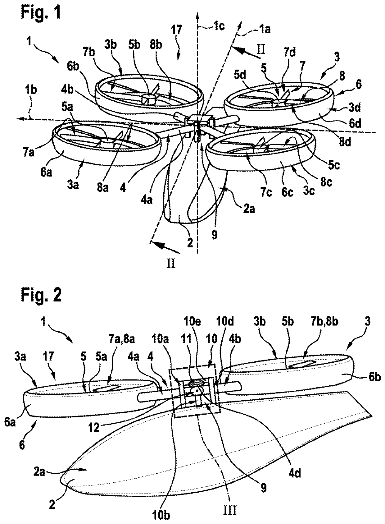
[0068]FIG. 1 shows a multirotor aircraft 1 with an aircraft airframe 2 according to the present invention. The airframe 2 defines a supporting structure of the multirotor aircraft 1.

[0069]The airframe 2 has an extension in longitudinal direction 1a, an extension in lateral direction 1b as well as an extension in vertical direction 1c and preferably defines an internal volume 2a. According to one aspect, the internal volume 2a is at least adapted for transportation of passengers, so that the multirotor aircraft 1 as a whole is adapted for transportation of passengers. The internal volume 2a is preferably further adapted for accommodating operational and electrical equipment, such as e. g. an energy storage system that is required for operation of the multirotor aircraft 1.

[0070]It should be noted that exemplary configurations of the internal volume 2a that are suitable for transportation of passengers, but also for accommodation of operational and electrical equipment, are readily av...


PUM


Abstract

A multirotor aircraft with an airframe and a thrust producing units arrangement, wherein the thrust producing units arrangement comprises a predetermined number of thrust producing units for producing thrust in a predetermined direction, and wherein a flexible suspension unit is rigidly mounted to the airframe, wherein the flexible suspension unit comprises at least one bearing that mechanically couples the thrust producing units arrangement to the airframe such that the thrust producing units of the predetermined number of thrust producing units are inclinable in relation to the airframe.

Description

CROSS-REFERENCE TO RELATED APPLICATIONS[0001]This application claims priority to European patent application No. EP 17400009.1 filed on Feb. 28, 2017, the disclosure of which is incorporated in its entirety by reference herein.BACKGROUND OF THE INVENTION(1) Field of the Invention[0002]The invention is related to a multirotor aircraft with an airframe and a thrust producing units arrangement that comprises a predetermined number of thrust producing units for producing thrust in a predetermined direction.2) Description of Related Art[0003]Various conventional multirotor aircrafts are known, e. g. from the documents EP 2 551 190 A1, EP 2 551 193 A1, EP 2 551 198 A1, EP 2 234 883 A1, WO 2015 / 028627 A1, U.S. Pat. No. D678 169 S, U.S. Pat. No. 6,568,630 B2, U.S. Pat. No. 8,393,564 B2, U.S. Pat. No. 7,857,253 B2, U.S. Pat. No. 7,946,528 B2, U.S. Pat. No. 8,733,690 B2, US 2007 / 0034738 A1, US 2013 / 0118856 A1, DE 10 2013 108 207 A1, GB 905 911 and CN 2013 06711 U. Other multirotor aircrafts a...

Claims


Application Information

Patent Timeline
Patent Type & Authority Patents(United States)
IPC IPC(8): B64C27/52B64C27/08B64C27/20B64C27/00B64C27/28B64C29/00
CPCB64C27/52B64C27/00B64C27/08B64C27/20B64C27/28B64C29/00B64C29/0033B64C2201/024B64C2201/108B64C2201/162B64C27/12B64D27/02B64U10/10B64U30/20B64U50/14
Inventor ZHANG, QINYINKIESEWETTER, UWEMORES, SEBASTIANSCHNEEBERGER, MARCOBEBESEL, MARIUS
Owner AIRBUS HELICOPTERS DEUT GMBH
Why Eureka
Try Eureka