
Balanced drying system

a drying system and balanced technology, applied in drying machines, lighting and heating equipment, furniture, etc., can solve the problems of difficult to timely and effectively control the air volume according to actual drying requirements, not having a very good automatic control function, and high operator skill, so as to reduce the input and operating costs of subsequent exhaust air treatment, simplify the equipment pipeline, and reduce the effect of heating energy consumption

Active Publication Date: 2021-05-04
VERBOCA ENERGY SAVING TECH CO LTD
View PDF20 Cites 0 Cited by
  • Summary
  • Abstract
  • Description
  • Claims
  • Application Information

AI Technical Summary

Benefits of technology

[0009]The technical problem to be solved by the present invention is to provide a balanced drying system, which can fundamentally achieve the purpose of energy conservation and emission reduction, and at the same time effectively solve the problems of system matching and adjustment, excessive exhaust air volume, excessive heating energy consumption, potential safety hazards, and great environmental protection cost present in the conventional drying system.
[0023]A Balanced Drying System Embodying the Present Invention has the Following Beneficial Effects Compared to the Prior Art:
[0024]The unit air inlet and the unit air outlet of the drying unit of the balanced drying system of the present invention are all connected with the air supply and exhaust main pipeline, so that the unit air inlets of the drying units are connected with the unit air outlets of the adjacent drying units via the air supply and exhaust main pipeline to form a series connection structure. The equipment pipeline is simplified, and the air pressure in the drying oven is automatically balanced in the air supply and exhaust main pipeline. The adjustment is simple, and the air volume required by the drying system is successively entered in each drying oven for drying and sweeping of the material to be dried. The air volume is adjusted according to the safe solvent concentration of the drying system. The unit air volume adjustment is simple and does not affect other units. The air and the contained heat are directly reused until the final drying unit is discharged from the drying system, and thus the heating energy consumption is reduced to a minimum level. In addition, the exhaust air emission volume determines the exhaust air volume to be subsequently treated. The balanced drying system makes the input and operating costs of subsequent exhaust air treatment significantly reduced. The exhaust air concentration at the air outlet of the last group of drying unit passed by the drying air of the system is the highest concentration point of the entire drying system. The single point online monitoring is implemented at the highest exhaust air concentration point, so that enterprises can easily implement the entire process control of production. The air exhaust volume of the drying system is adjusted according to the exhaust air concentration so as to ensure the exhaust air concentration is below the safety limit, and thus the situation of the entire dry system is safe as long as the situation of a point is safe, which completely eliminates explosion hazard of the production equipment. Therefore, the present invention has the advantages of a simple and stable system, simple adjustment, low air exhaust volume and thus low energy consumption, no safety hazards, low environmental protection cost and the like.
[0025]The balanced drying system of the present invention can improve the current development difficulties of high energy consumption, high cost of waste gas treatment and potential safety hazards faced by industries such as packaging printing and coating and painting, fundamentally reduce production costs, completely eliminates explosion hazard of the production equipment, and achieved complete energy conservation and emission reduction. In the current severe environmental protection dilemma, it completely solves the problem that the enterprise's market competitiveness is not strong or even affects the survival of enterprises. It greatly facilities the development of packaging printing and coating and painting industries.

Problems solved by technology

At present, the drying system of most production equipments does not have a very good automatic control function.
The adjustment of the multiple air valves also requires highly for the skill of the operator and it is difficult to timely and effectively control the air volume according to actual drying requirements.
If the air exhaust is insufficient, safety accidents or product quality accidents may easily occur.
Excess hot exhaust air is discharged into the air, causing energy waste and air pollution that is difficult to control.
However, the results are still not satisfactory, and there is still great room for improvement of the drying system in terms of energy saving and emission reduction.
For the sake of safety, it is necessary for the multi-unit drying system with automatic control function to be provided in each unit with VOC gas concentration monitors, leading to complex systems, poor reliability and large investment.
Dust and humidity increase due to weather changes or workshop hygiene and cleaning, which will affect the production process and the quality of finished products.
However, because the air exhaust is a multi-point regulation which would have mutual influence, the air pressure difference between each point of the system is relatively large, will easily cause leakage of exhaust air of drying oven.
The smaller the circulating air volume of the drying unit is, the more difficult it is to adjust the balance.
In addition, this needs only repeated manual adjustments based on hand feeling, which is tedious and difficult to cope with.
Lack of experience will lead to the dilemma of poorer situation by more adjustments.
Therefore, in the actual production, fine adjustment usually is not performed by production operators via valves.
Taking the gravure printing machine as an example, the actual running air volume is often nearly 10 times that of the conservatively calculated safe air volume, which greatly increases the heating energy consumption and the fan operating power.
At the same time, the increase of the exhaust air volume also increases the input and operation costs of the subsequent exhaust air treatment.
This imposes higher degree of difficulty for user's operation and achievement of target detection.
However, the consumption energy of the drying oven becomes larger.
When the amount of solvent used in the unit printing is large or the return air ratio is large, even if the total exhaust air volume is great, the unit exhaust air volume may still be insufficient.
There may be a case where the solvent concentration in the dry air exceeds the lower safety limit, and there is a safety risk of explosion.
To sum up, the traditional drying system has the following problems: difficulty in system matching and adjustment, excessive exhaust air volume, excessive heating energy consumption, potential safety hazards, and great environmental protection cost.

Method used


Image

  • Balanced drying system
  • Balanced drying system

Examples


embodiment 1

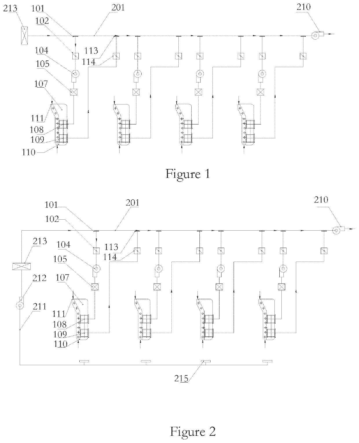
[0031]taking a gravure printing machine as an example, referring to FIG. 1, the balanced drying system is described as follows.

[0032]The balanced drying system of this embodiment comprises an air supply and exhaust main pipeline 201, an air exhaust fan 210, and at least two groups of drying units. The drying units each comprises a unit air supply fan 104 and a drying oven 107, the drying units each is provided with a unit air inlet 101 and a unit air outlet 113, the drying oven 107 is provided with a drying oven air inlet 108 and a drying oven air outlet 109, and all of the groups of the drying units are disposed in pairs at intervals on the air supply and exhaust main pipeline 201 via the unit air inlet 101 and the unit air outlet 113, the unit air inlet 101 is connected with the drying oven air inlet 108, and the unit air outlet 113 is connected with the drying oven air outlet 109. One end of the air supply and exhaust main pipeline 201 is an air exhaust end and is connected with ...

embodiment 2

[0041]taking a gravure printing machine as an example, referring to FIG. 2, a description will be made on a balanced drying system that sucks air from the bottom of the printing unit for centralized air supply.

[0042]As in the balanced drying system described in the embodiment 1 and the modified embodiment 1, the air supply and exhaust main pipeline 201 simply and directly intakes the air from the external environment of the system. The embodiment 2 has a form of air intake that can deal with both exhaust air leakage and air exhaust from volatile solvent of the ink duct, that is, the air intakes is a centralized air supply. Based on the above embodiment 1, the balanced drying system further comprises an air supply fan 212 and at least two air collection slots 215, wherein the air supply end of the air supply and exhaust main pipeline 201 is provided with a plurality of air supply inlets each corresponding to one group of drying units, the air collection slots 215 are disposed at the ...

embodiment 3

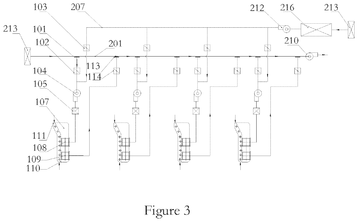
[0043]taking a gravure printing machine as an example. Referring to FIG. 3, the centralized heating of the balanced drying system is described as follows:

[0044]Compared with embodiment 1, the main difference is that for the balanced drying system, a hot air main pipeline after being externally heated can be centralized for supplying hot air for several drying units. That is, based on the above embodiment 1, the balanced drying system further comprises a hot air main pipeline 207, an air supply fan 212, a hot air stove 216, an air supply filter 213 and at least two hot air valves 103. The hot air main pipeline 207 is provided with a plurality of hot air outlets connected in parallel and each corresponding to one group of drying units, the hot air outlets each is connected with the unit air inlet 101, the hot air valves 103 each is disposed between the hot air outlet and the unit air inlet 101, and the air supply fan 212, the hot air stove 216 and the air supply filter 213 are all arr...


PUM


Abstract

The invention provides a balanced drying system, comprising an air supply and exhaust main pipeline, and at least two groups of drying units; the drying units each comprises a unit air supply fan and a drying oven, the drying units each is provided with a unit air inlet and a unit air outlet, the drying oven is provided with a drying oven air inlet and a drying oven air outlet, and all of the groups of the drying units are disposed in pairs at intervals on the air supply and exhaust main pipeline via the unit air inlet and the unit air outlet, the unit air inlet is connected with the drying oven air inlet, and the unit air outlet is connected with the drying oven air outlet. The invention has the advantages of concise and stable system, simple adjustment, low exhaust air volume, low energy consumption and the like.

Description

FIELD OF THE INVENTION[0001]The invention relates to the field of energy conservation and emission reduction, and relates to a multi-unit hot air drying process in packaging printing, coating and painting industries, particularly, relates to production equipments of that require hot air drying, such as a gravure printing machine, a laminating machine, a coating machine, and furniture painting.BACKGROUND OF THE INVENTION[0002]Drying system is the main energy consumption unit for printing, laminating, coating, spraying and paint spraying equipments. It is also the main emission source of exhaust air. The performance of the drying system is the core parameter of performance evaluation indicators of the production equipment.[0003]At present, the drying system of most production equipments does not have a very good automatic control function. When operating, the operating status of the drying system needs to be manually adjusted by the operators based on their practical experience. The a...

Claims


Application Information

Patent Timeline
Patent Type & Authority Patents(United States)
IPC IPC(8): F26B9/06F26B25/00F26B21/00F26B3/04F26B21/04
CPCF26B9/063F26B9/06F26B21/00F26B21/001F26B21/003F26B25/00F26B25/007F26B21/006F26B21/04F26B3/04
Inventor JIAN, SUDUAN, YUANMIN
Owner VERBOCA ENERGY SAVING TECH CO LTD
Learn More