Valve timing controller and valve timing control method
a timing controller and valve technology, applied in the direction of electric control, ignition automatic control, engine starters, etc., can solve the problem of not enough study regarding the timing phase to be changed, and achieve the effect of improving the timing
- Summary
- Abstract
- Description
- Claims
- Application Information
AI Technical Summary
Benefits of technology
Problems solved by technology
Method used
Image

Examples
first embodiment
A. First Embodiment
[0017]A-1. Device Configuration:
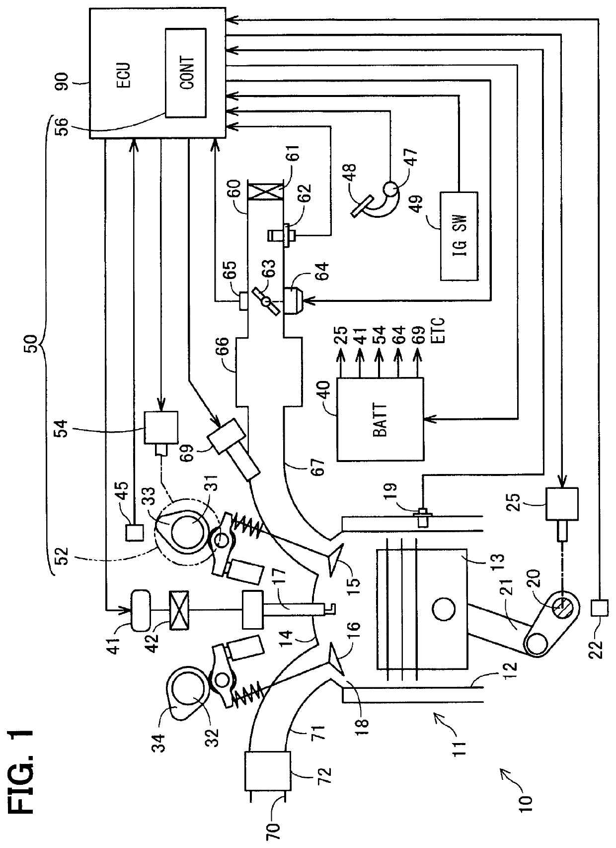
[0018]An internal-combustion engine system 100 shown in FIG. 1 is mounted on a vehicle (not shown) and used as a power source. The internal-combustion engine system 100 includes an internal-combustion engine 10, a battery 40, a valve timing controller 50, and an electronic control unit 90.
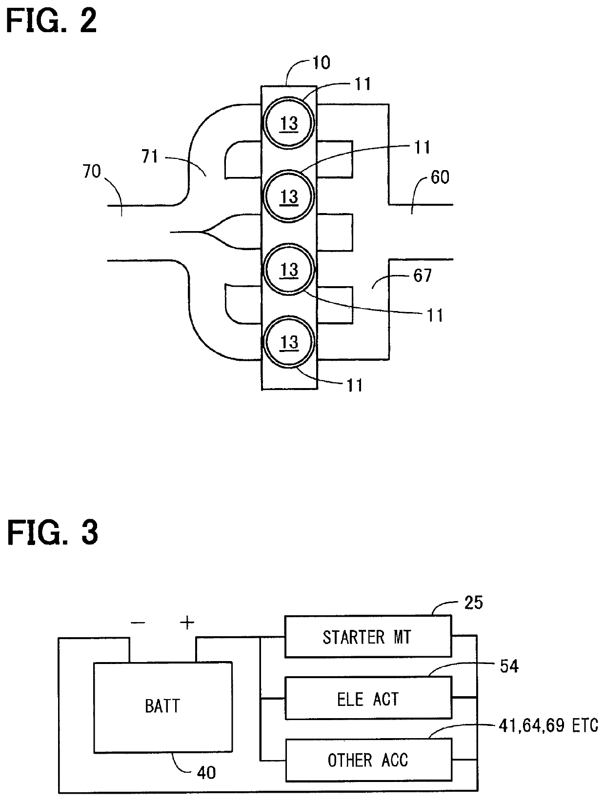
[0019]As shown in FIG. 2, the internal-combustion engine 10 is configured by an in-line four-cylinder intake port injection type engine in which four cylinders 11 are arranged in series. As shown in FIG. 1, the internal-combustion engine 10 includes a cylinder 11, a crankshaft 20, an intake camshaft 31, and an exhaust camshaft 32. In FIG. 1, for convenience of illustration, only one cylinder 11 and a pipe system connected to the cylinder 11 are shown. The internal-combustion engine 10 is connected to an intake pipe 60 and an exhaust pipe 70, respectively.
[0020]The intake pipe 60 functions as a flow passage for supplying air to the internal-combusti...
second embodiment
B. Second Embodiment
[0062]In the start time control process performed by the valve timing controller 50 according to the second embodiment shown in FIG. 6, step S130a, which is different from the control process of step S130 in the first embodiment, is performed. The other configuration including the device configuration is the same as that of the valve timing controller 50 of the first embodiment, which means that the same configuration has the same reference numeral and the detailed description thereof is omitted.
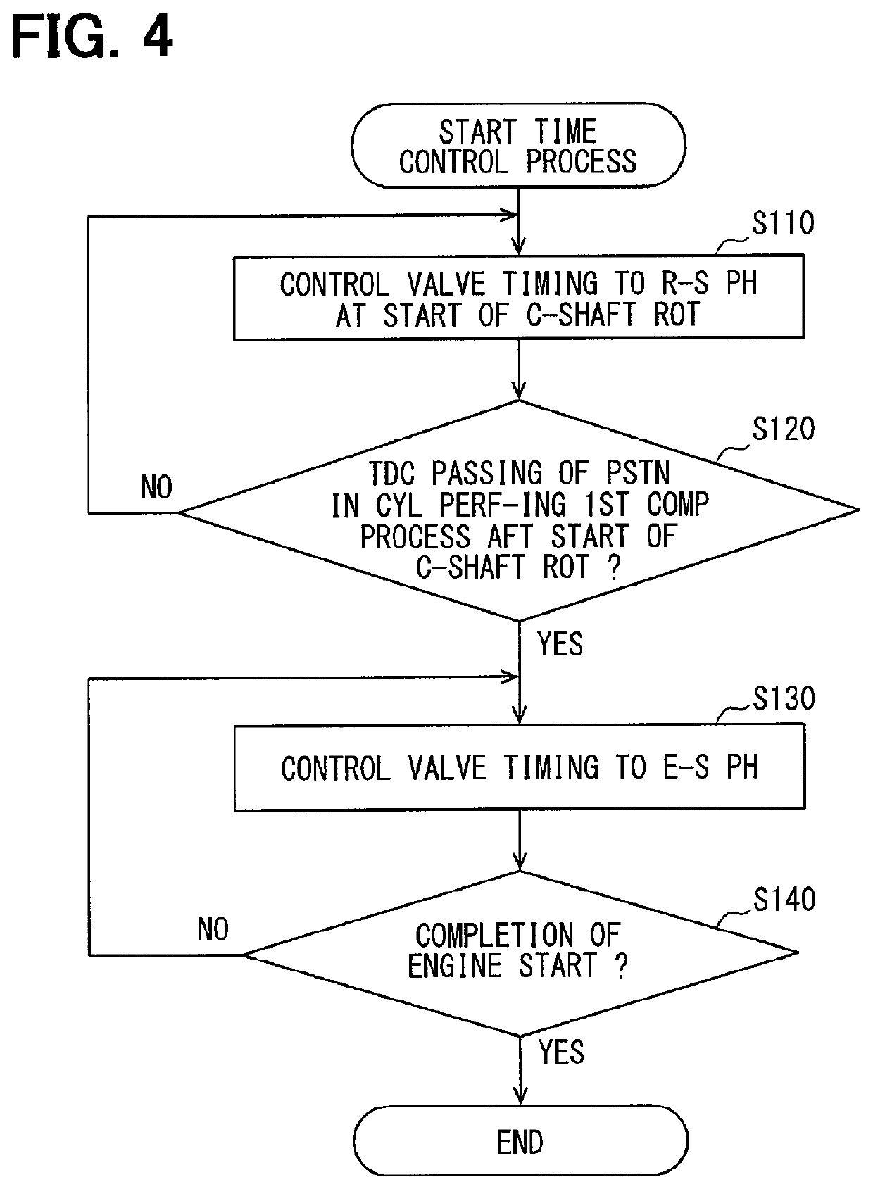
[0063]As shown in FIG. 6, when it is determined that the piston 13 of the cylinder 11 firstly performing the first compression process after the start of rotation of the crankshaft 20 passes the top dead center (step S120: YES), the process proceeds to S130a.
[0064]As shown in FIG. 7, in the following description, the cylinder 11 that firstly performs a compression process among the four cylinders after the start of rotation of the crankshaft 20 is also referred to as a f...
third embodiment
C. Third Embodiment
[0070]The start time control process performed by the valve timing controller 50 according to the third embodiment shown in FIG. 9 is characterized in that step S102 and step S104 are performed before step S110, which is different from the start time control process of the first embodiment. The other configuration including the device configuration is the same as that of the valve timing controller 50 of the first embodiment, thereby the same configuration has the same reference numeral and the detailed description thereof is omitted.
[0071]When the ignition switch 49 is turned ON to start the internal-combustion engine system 100, the control section 56 obtains temperature of the internal-combustion engine 10 (step S102). In the present embodiment, temperature detected by the cooling water temperature sensor 19 is obtained as temperature of the internal-combustion engine 10. The temperature of the internal-combustion engine 10 may be obtained not only by the cooli...
PUM
 Abstract
Description
Claims
Application Information