
Device for operating a radar device

a radar and sensor technology, applied in the direction of measurement devices, using reradiation, instruments, etc., can solve the problems of enlargement of the chip surface, high demands on the usable dynamic range of the receiver, and the limited dynamic range of the overall system, so as to achieve efficient protection and minimize the effect of the effect of the effect of the effect of the effect of the effect of the surface area

Active Publication Date: 2021-07-06
ROBERT BOSCH GMBH
View PDF13 Cites 0 Cited by
  • Summary
  • Abstract
  • Description
  • Claims
  • Application Information

AI Technical Summary

Benefits of technology

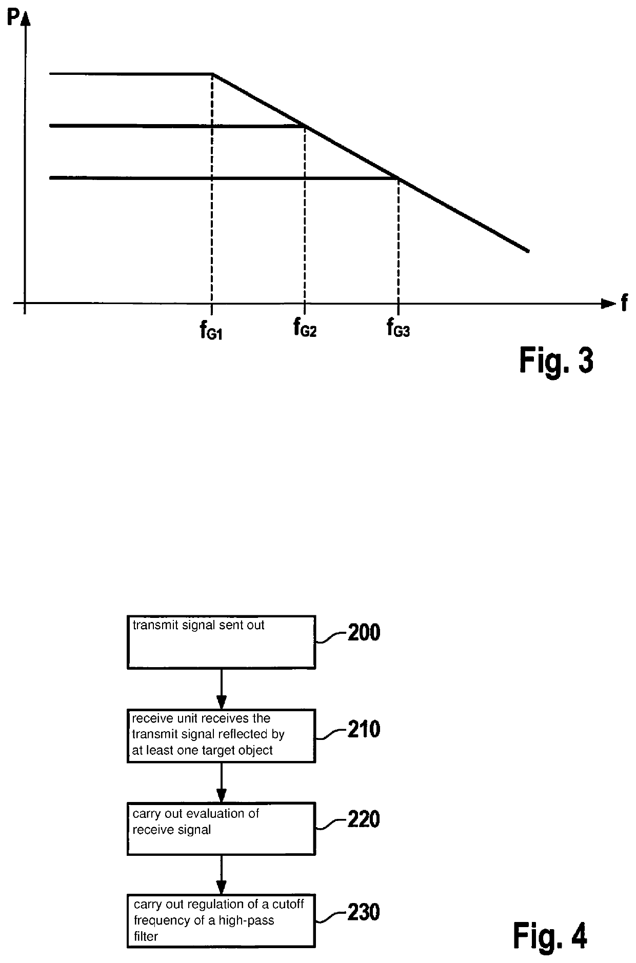
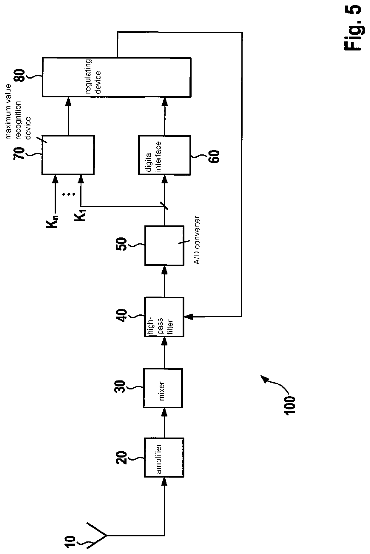
The present invention provides an improved method for operating a radar sensor that can adapt to the strength of the target being recognized. This is done by shifting the cutoff frequency of the high-pass filter upward as a function of the received signals, even when a strong target is nearby. The method can also set a defined number of cutoff frequencies based on the evaluated receive signal, allowing for a dynamic adaptation to the surrounding environment scenario. Additionally, the method includes identifying the presence of a frequency below a previously set value of the cutoff frequency and raising the value of the cutoff frequency if the power level of that frequency is greater than a predefined threshold. This method advantageously protects the analog-digital converter of the receive unit from saturation and ensures accurate target detection.

Problems solved by technology

Radar sensors for detecting the surrounding environment place high demands on the usable dynamic range of the receiver.
While analog blocks of the radar receiver have a very large dynamic range, a dynamic range of the overall system is limited by an analog-digital converter.
Each enlargement of the bit width of the converter, and thus of the dynamic range, results in an enlargement of the chip surface and increases the power loss, and has to be carefully weighed for reasons of cost and heat dissipation.
Despite careful design, it may occur that the receiver is overmodulated by a signal.
This is undesirable, because in this way new frequency components may arise that could be interpreted as targets.
This does remedy the overmodulation situation, but however also has the result that weak targets can no longer be detected.

Method used


Image

  • Device for operating a radar device
  • Device for operating a radar device
  • Device for operating a radar device

Examples


Embodiment Construction

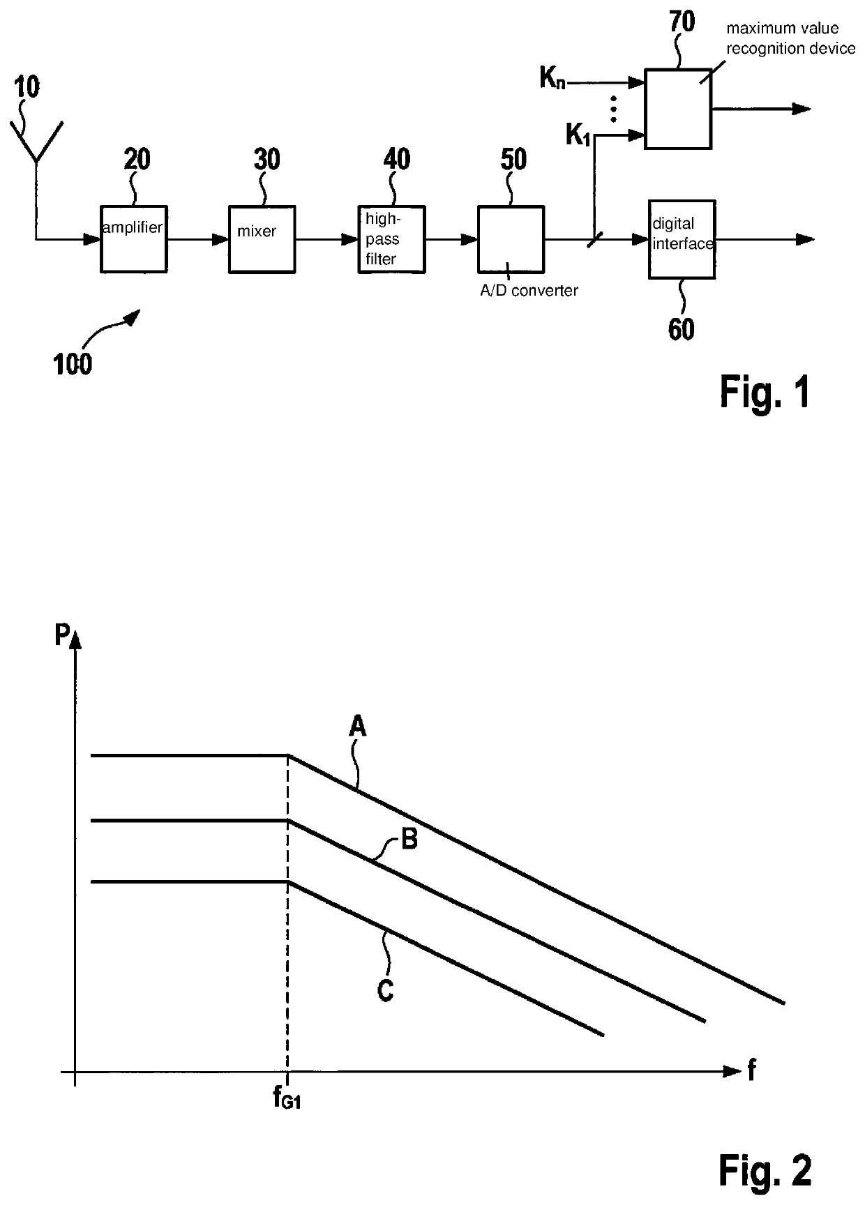
[0035]In accordance with the present invention, a cutoff frequency of a high-pass filter is adapted to receive signals in such a way that both strong near targets and weak remote targets can be detected well.

[0036]For this purpose, instead of regulating a gain level of a receive chain or a transmit power, a cutoff frequency of a high-pass filter used for a dynamic compression is regulated. If the receiver is designed in such a way that the cutoff frequency of the high-pass filter is within the usable frequency range, then by displacing the cutoff frequency upward a reduction of the receive level for near targets can be brought about, while remote targets are essentially not impaired. Because the level in the near range is very high even for small targets, but such targets often disappear in the noise in the far range, this proposed method can produce a performance advantage of the radar sensor.

[0037]FIG. 1 schematically shows a diagram of a receive unit 100 of a radar sensor. Receiv...


PUM


Abstract

A method for operating a radar sensor, having the steps: sending out a transmit signal; reception, by a receive unit, of the transmit signal reflected by at least one target object; evaluation of the receive signal; and regulation of a cutoff frequency of a high-pass filter as a function of the evaluated receive signal.

Description

FIELD[0001]The present invention relates to a method for operating a radar sensor. The present invention also relates to a radar sensor.BACKGROUND INFORMATION[0002]Radar sensors for detecting the surrounding environment place high demands on the usable dynamic range of the receiver. The dynamic is determined by two components. The first component is a distance dynamic characteristic. The greater the distance from the target object is, the lower the receive level. The radar equation shows that the level of a point target decreases by about 40 dB per decade. The second component is the dynamic characteristic of the backscatter or radar cross-section (RCS). While for example a pedestrian reflects only a low power level, a truck for example produces a much higher power level in the receiver.[0003]The named components have some effects on each other. If a target can no longer be regarded as a point target, but rather is large relative to the antenna lobe, it is no longer completely illum...

Claims


Application Information

Patent Timeline
Patent Type & Authority Patents(United States)
IPC IPC(8): G01S7/35G01S13/42G01S13/931G01S13/00
CPCG01S7/354G01S13/42G01S13/931
Inventor STEINBUCH, DIRKMOERTLBAUER, KARINSTEINHAUER, MATTHIASOTT, MICHAEL
Owner ROBERT BOSCH GMBH
Learn More