
Conductive atomic force microscopy system with enhanced sensitivity and methods of using such a system

a technology of atomic force microscopy and enhanced sensitivity, which is applied in scanning probe microscopy, instruments, measurement devices, etc., can solve the problems of day c-afm systems, difficult to measure the concentration level of low-dopant,

Active Publication Date: 2021-11-16
GLOBALFOUNDRIES US INC
View PDF13 Cites 0 Cited by
  • Summary
  • Abstract
  • Description
  • Claims
  • Application Information

AI Technical Summary

Benefits of technology

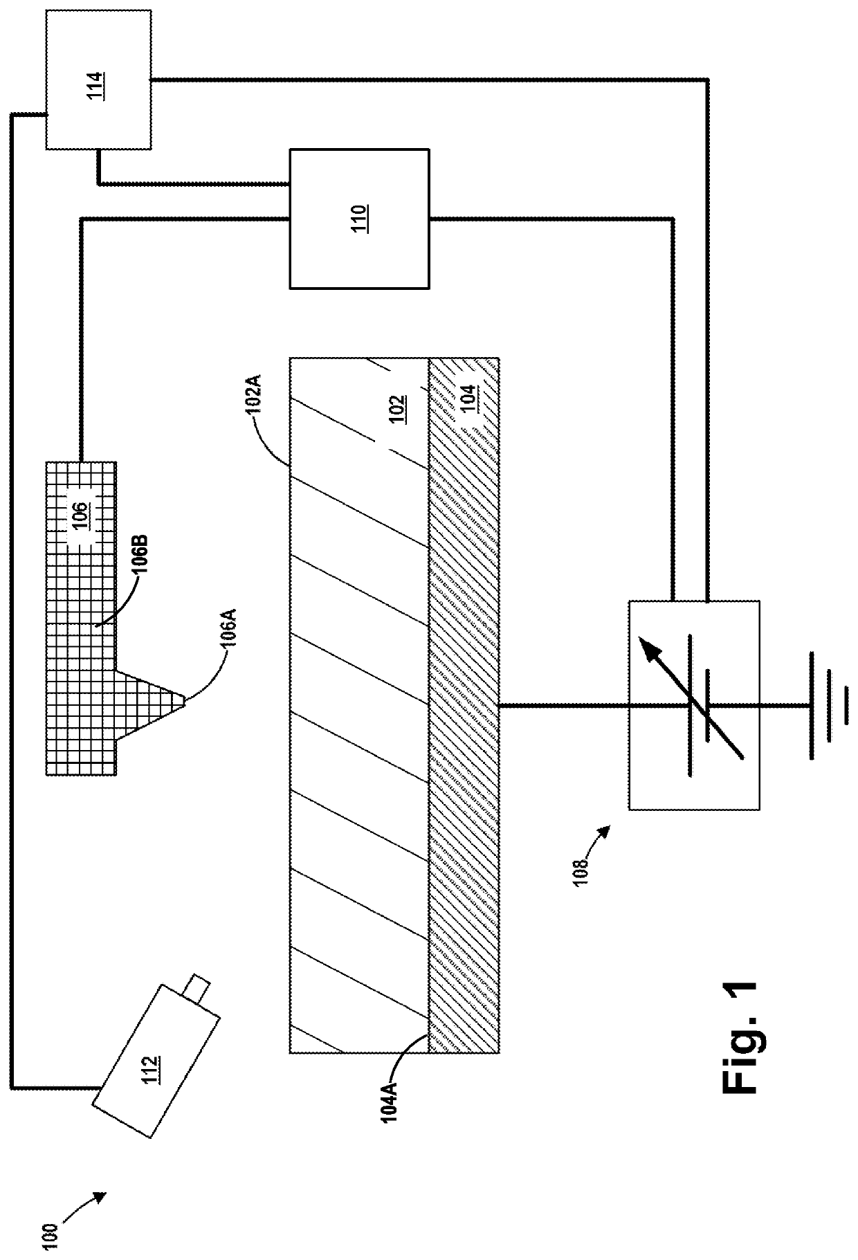
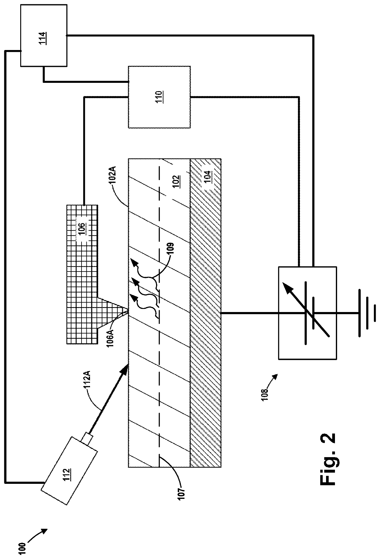
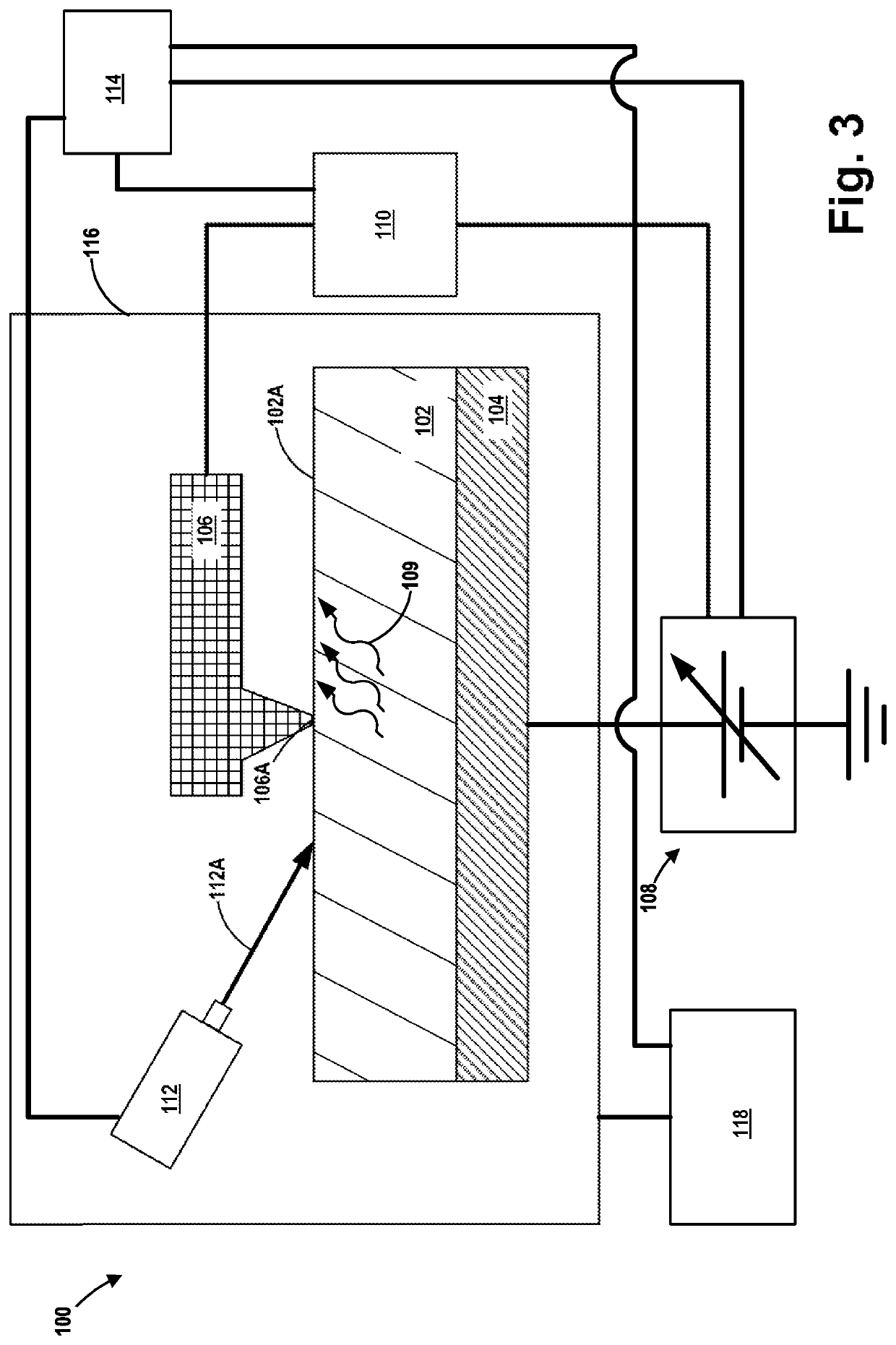
The present invention provides a C-AFM system with enhanced sensitivity and various methods of using it for measuring electrical-related parameters of doped semiconductor materials and device structures. The methods involve irradiating the materials with radiation and measuring the electrical current that flows through the materials using a measure device that is operatively coupled to a cantilever beam probe. The invention has technical effects in terms of increased sensitivity and accuracy in measuring electrical-related parameters of materials.

Problems solved by technology

However, such lower dopant concentration levels are difficult to measure using current-day C-AFM systems.

Method used


Image

  • Conductive atomic force microscopy system with enhanced sensitivity and methods of using such a system
  • Conductive atomic force microscopy system with enhanced sensitivity and methods of using such a system
  • Conductive atomic force microscopy system with enhanced sensitivity and methods of using such a system

Examples


Embodiment Construction

[0011]Various illustrative embodiments of the invention are described below. In the interest of clarity, not all features of an actual implementation are described in this specification. It will of course be appreciated that in the development of any such actual embodiment, numerous implementation-specific decisions must be made to achieve the developers' specific goals, such as compliance with system-related and business-related constraints, which will vary from one implementation to another. Moreover, it will be appreciated that such a development effort might be complex and time-consuming but would nevertheless be a routine undertaking for those of ordinary skill in the art having the benefit of this disclosure.

[0012]The present subject matter will now be described with reference to the attached figures. Various structures, systems and devices are schematically depicted in the drawings for purposes of explanation only and so as to not obscure the present disclosure with details t...


PUM


Abstract

An illustrative method disclosed herein includes measuring at least one electrical-related parameter of a doped semiconductor material by simultaneously irradiating at least a portion of an upper surface of the doped semiconductor material, urging a conductive tip of a cantilever beam probe into conductive contact with the upper surface of the irradiated portion of the doped semiconductor material, and generating an electrical current that flows through the doped semiconductor material, through a measurement device that is operatively coupled to the cantilever beam probe and through the cantilever beam probe, wherein the measurement device measures the at least one electrical-related parameter of the doped semiconductor material.

Description

FIELD OF THE INVENTION[0001]The present disclosure is directed to various novel embodiments of a conductive atomic force microscopy (C-AFM) system with enhanced sensitivity and various novel methods of using such a C-AFM system.BACKGROUND[0002]Manufacturers of integrated circuit products rely on a variety of metrological tools to help control process operations and identify device failures. For example, C-AFM systems may be used for measuring a variety of parameters, e.g., dopant concentration levels, grain boundary resistance values, resistance across interfacial films, etc. In terms of resistance measurements, a typical C-AFM system is accurate up to about 0.1-1.0Ω. In terms of dopant concentrations, the cited range for the resistance values typically corresponds to a semiconductor substrate having a dopant concentration of about 1e14′-1e17 ions / cm3. However, in some products, e.g., waveguides on a silicon photonics product, it is desirable for the semiconductor substrate to have ...

Claims


Application Information

Patent Timeline
IPC IPC(8): G01Q30/16G01Q60/24
CPCG01Q30/16G01Q60/24G01Q60/30G01Q60/40
Inventor MODY, JAYDIXIT, HEMANT
Owner GLOBALFOUNDRIES US INC
Learn More