
Clock synthesis circuitry and associated techniques for generating clock signals refreshing display screen content

a clock signal and clock synthesis technology, applied in the direction of generating/distributing signals, pulse generation by logic circuits, pulse techniques, etc., can solve the problems of steady state error voltage, complicated mathematical analysis and many elements of its operation, etc., to reduce visual effects, reduce real estate, and facilitate the implementation of spread spectrum

Active Publication Date: 2021-11-16
PLANAR SYSTEMS
View PDF12 Cites 0 Cited by
  • Summary
  • Abstract
  • Description
  • Claims
  • Application Information

AI Technical Summary

Benefits of technology

The solution provides synchronized and predictable clock pulses, reducing visual artifacts, improving refresh accuracy, and minimizing silicon costs by eliminating the need for bulky analog components, while enabling efficient EMI reduction and precise clock control.

Problems solved by technology

And conceptually, the operation of the PLL is relatively simple, but the mathematical analysis and many elements of its operation can become complicated.
When the PLL is in lock, a steady state error voltage is produced.

Method used


Image

  • Clock synthesis circuitry and associated techniques for generating clock signals refreshing display screen content
  • Clock synthesis circuitry and associated techniques for generating clock signals refreshing display screen content
  • Clock synthesis circuitry and associated techniques for generating clock signals refreshing display screen content

Examples


Embodiment Construction

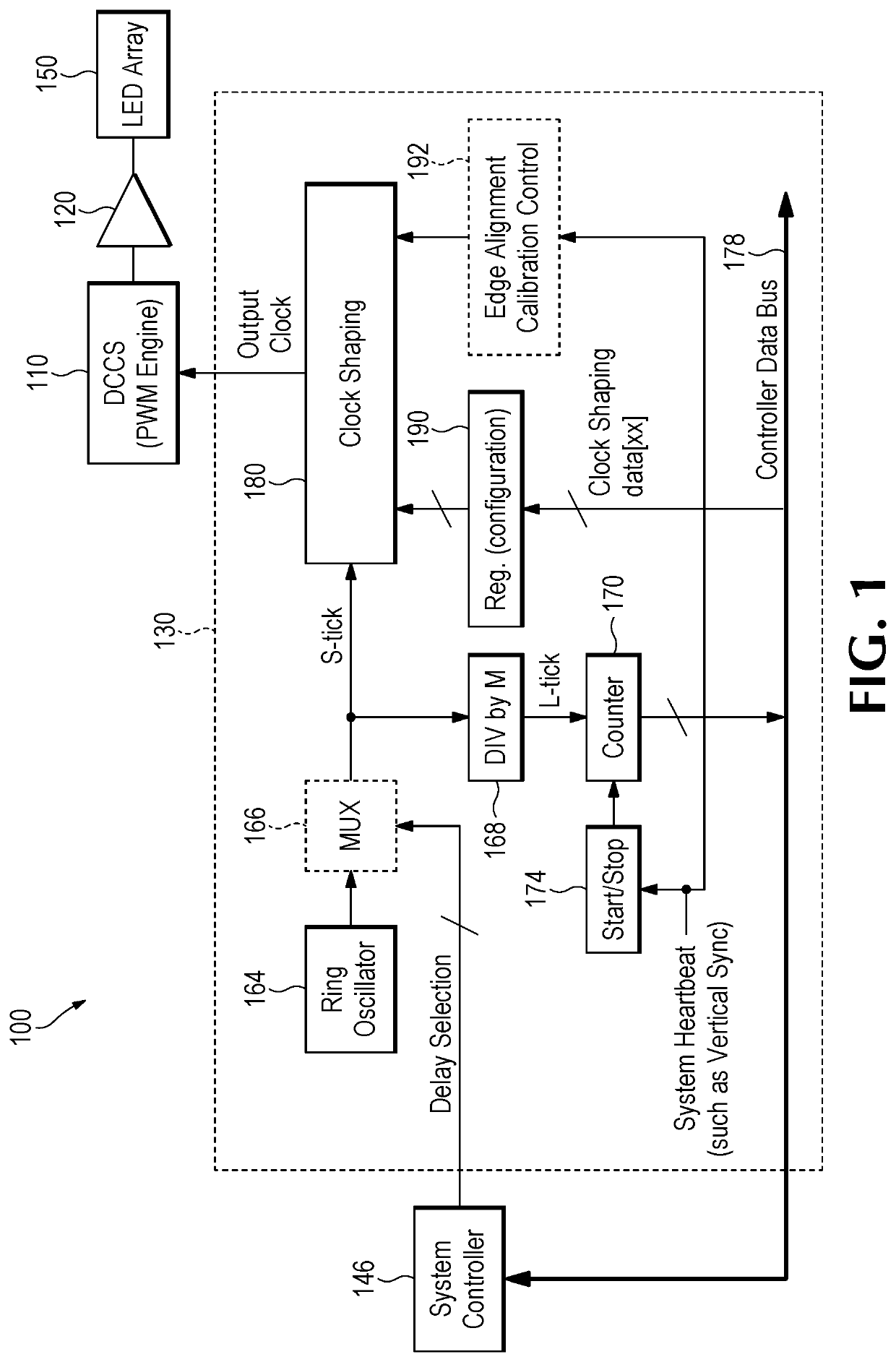
[0041]PLLs are prevalent features of integrated circuits (ICs) such as System On Chip (SOC) attempts. For example, PLLs are used in LED driver attempts of the type employed in large-scale digital signage applications. They are used due to difficulties in implementing a centralized clock across many logic components and PCB devices in the system. In such environments, PLLs produce accurate clocks facilitating a regularized synchronicity across all LED drivers based on a vertical synchronization (vertical sync) signal timing that defines a frame update and calls for delivery of new frame content to be displayed.

[0042]Although PLL designs are a versatile building block in IC design electronics today, and a common means to attempt to solve clock synchronization in electronic system designs, the PLL paradigm is complex and expensive in implementation. Some design alternatives are feasible in certain implementations of PLLs, but they mostly still rely on bulky analog implementation of the...


PUM


Abstract

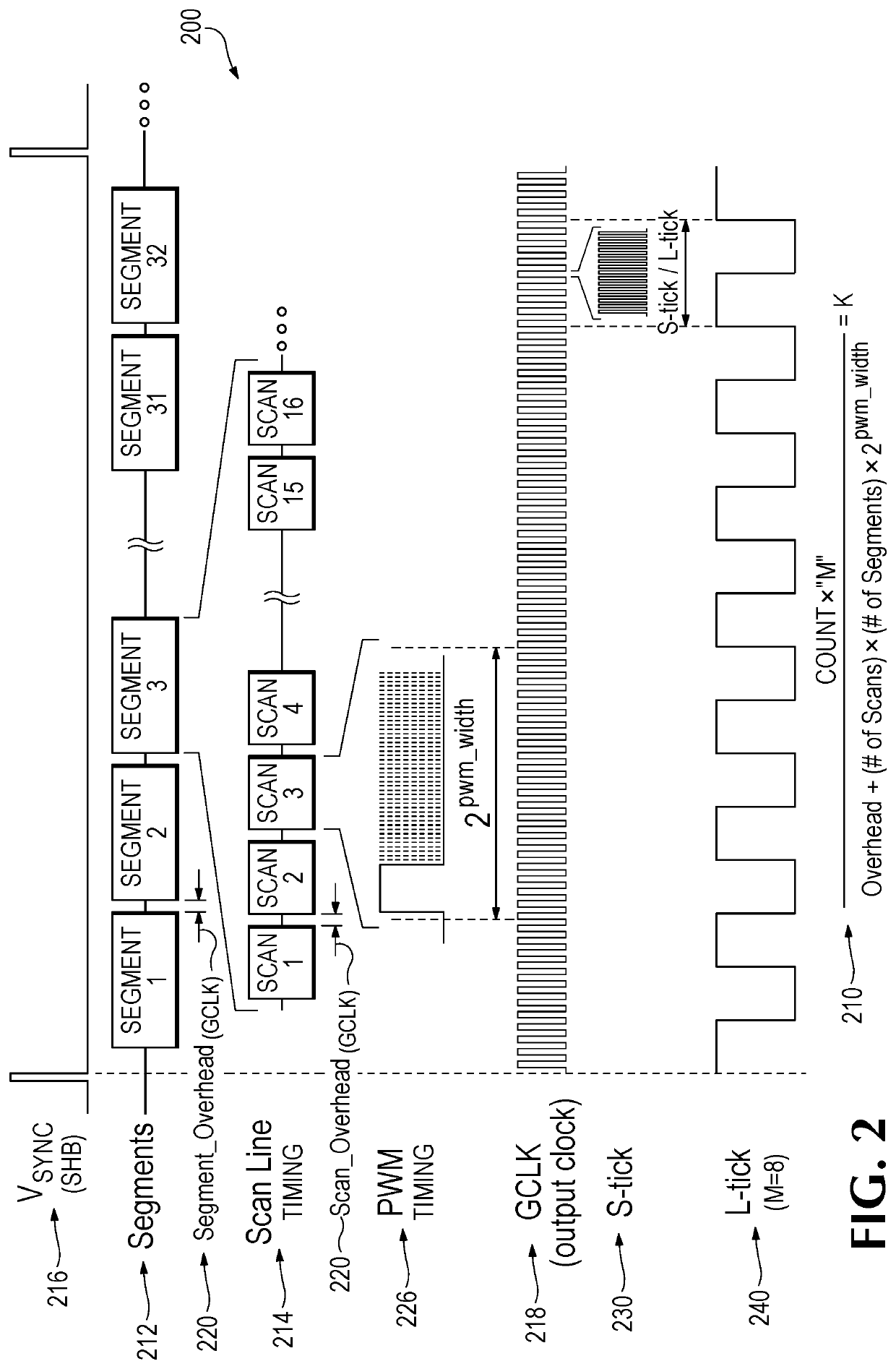
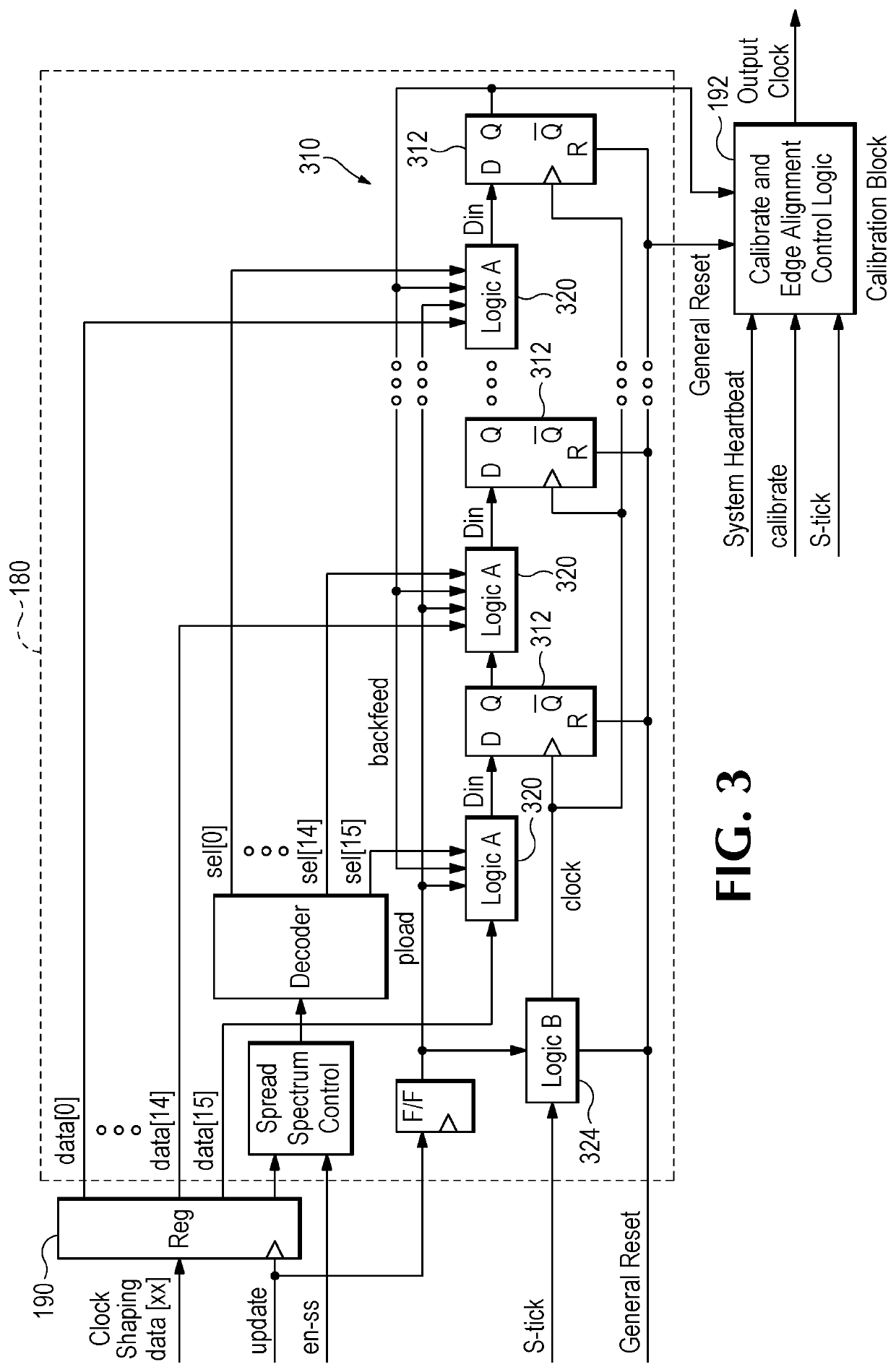
A clock synthesis circuit and method provides for precision controlling and programming a selected number of clock pulses (or simply “clocks”) fitted within time periods between two consecutive pulses of a so-called system heartbeat (SHB) timing signal. The disclosed embodiments have applicability in light emitting diode (LED) display driver integrated circuits (ICs) and, more generally, digital circuits including computer processors, microcontrollers, logic devices such as field-programmable gate arrays (FP-GA), and other logic circuitry.

Description

RELATED APPLICATION[0001]This application is a National Stage of International Application No. PCT / US2018 / 046111, filed Aug. 9, 2018, which claims priority benefit of U.S. Provisional Patent Application No. 62 / 543,321, filed Aug. 9, 2017, which are hereby incorporated by reference in their entireties.TECHNICAL FIELD[0002]This disclosure relates generally to driver circuits used for light emitting diodes (LEDs), and more particularly, to generating timing signals delivered to a driver circuit used for refreshing screen content by driving an array of LEDs present in digital signage displays and similar display applications including light sources for general illumination, signs and signals, display panels, televisions, and other applications. Irrespective of the particular application, LED driver circuits typically supply power to the LEDs, and this disclosure in turn relates to clock circuitry that controls the delivery and refreshing of visual content presented on a display screen.B...

Claims


Application Information

Patent Timeline
Patent Type & Authority Patents(United States)
IPC IPC(8): H03K3/017G06F1/04H03K3/027H03K3/84H05B45/325
CPCH03K3/017G06F1/04H03K3/027H03K3/84H05B45/325
Inventor NADERSHAHI, SHAHNAD
Owner PLANAR SYSTEMS
Learn More