Process for converting a feedstock containing pyrolysis oil

a technology of pyrolysis oil and feedstock, which is applied in the direction of hydrocarbon oil treatment, thermal non-catalytic cracking, and solvent de-asphalting, etc., to achieve the effect of reducing equipment fouling, reducing coke precursors and sediment formation, and reducing equipment fouling

Active Publication Date: 2021-12-28
AXENS SA
View PDF8 Cites 0 Cited by
  • Summary
  • Abstract
  • Description
  • Claims
  • Application Information

AI Technical Summary

Benefits of technology

[0023]The process thus enables the profitable exploitation of the pyrolysis oil by converting it into light finished products, by combining this oil (the “first” feedstock) with a conventional heavy hydrocarbon-based feedstock (the “second” feedstock) to make it undergo a hydroconversion (the term “conventional” means that it is the type of feedstock, illustrated later, which usually feeds hydroconversion devices / processes), but under specific conditions. Specifically, according to the invention, the temperatures at which each of the two types of feedstock are introduced into the hydroconversion reactor are controlled and selected, with a lower feed temperature for the pyrolysis oil than for the heavy hydrocarbon-based feedstock. This choice proved to make it possible to eliminate, or at the very least to minimize, the risk of formation of gums in or upstream of the reactor, which would originate from the polymerization of the olefins contained in the oil when it is introduced into the reactor at an excessively high temperature.
[0054]Preferably, the hydroconversion step a) is performed in the presence of a colloidal or molecular catalyst, and of a porous supported catalyst. Specifically, the presence of a colloidal or molecular catalyst in the reaction zone makes it possible to treat the asphaltenes more efficiently, and thus to reduce the formation of coke precursors and of sediments. The use of a colloidal catalyst enables a reduction of the fouling of the equipment and an increased degree of conversion.

Problems solved by technology

a) ebullated-bed hydroconversion of a feedstock, in the presence of hydrogen, in a hydroconversion section comprising at least one three-phase reactor,
b) atmospheric fractionation of at least a portion of the hydroconverted liquid effluent obtained from step a) in an atmospheric fractionation section to produce a fraction comprising a gasoline cut and a gas oil cut, and an atmospheric residue;
c) fractionation under vacuum of at least a portion of the atmospheric residue obtained from step b) in a vacuum fractionation section to obtain a vacuum gas oil fraction comprising light vacuum gas oils (LVGO) and heavy vacuum gas oils (HVGO), and an unconverted vacuum residue fraction,
d) deasphalting of at least a portion of the unconverted vacuum residue fraction obtained from step c) in a deasphalting section to obtain an asphaltene-depleted hydrocarbon-based cut known as the deasphalted oil, and residual asphalt,
e) liquid-liquid extraction on the asphaltene-depleted hydrocarbon-based cut in an aromatics extraction section using a polar solvent to extract aromatics to produce an extract enriched in aromatics and resins and a raffinate depleted in aromatics and resins, the extract being sent at least partly as aromatic diluent to the inlet of the hydroconversion section. This process does not seek to profitably exploit the pyrolysis oil.

Method used


Image

  • Process for converting a feedstock containing pyrolysis oil
  • Process for converting a feedstock containing pyrolysis oil
  • Process for converting a feedstock containing pyrolysis oil

Examples


example 1

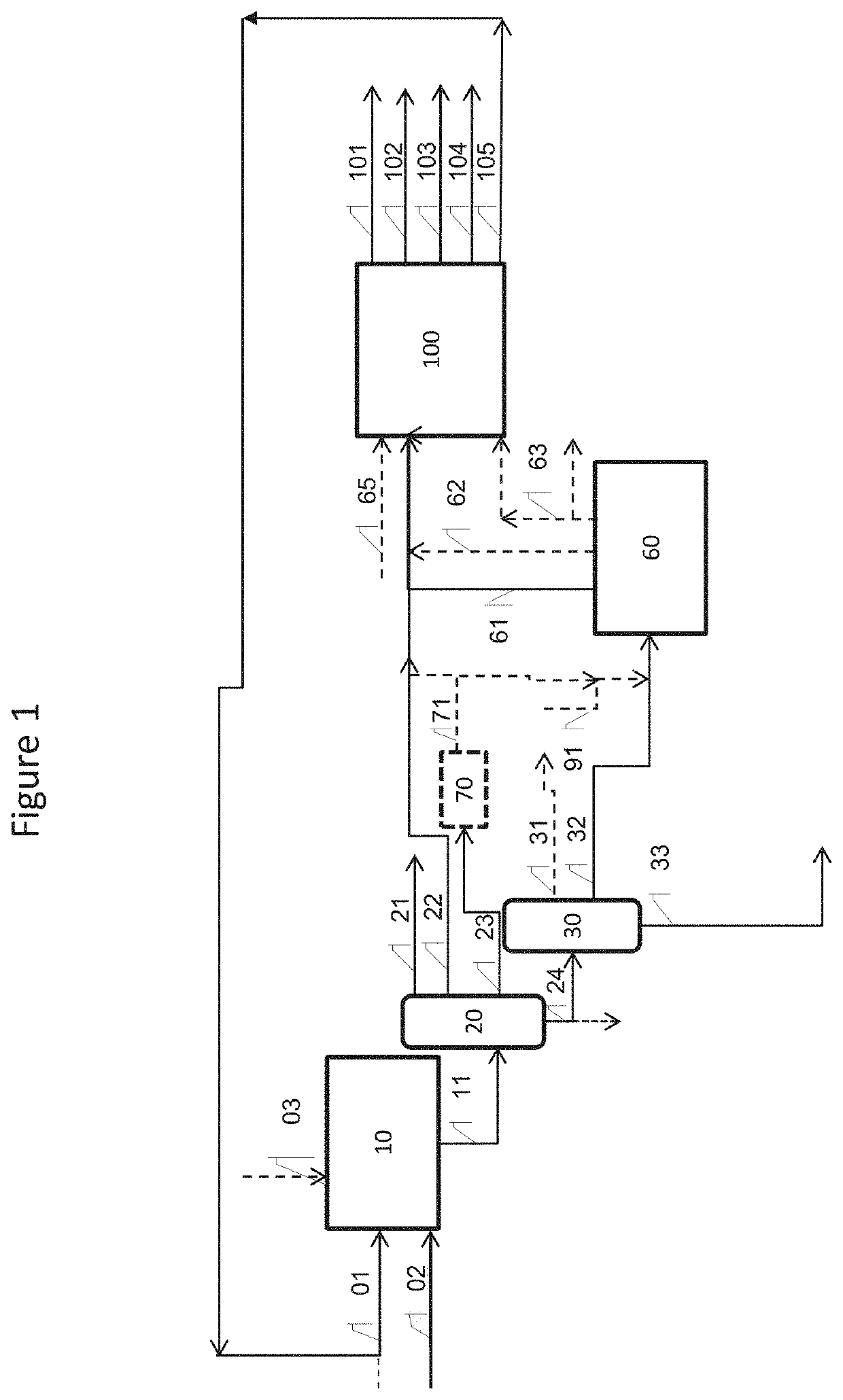
[0220]This non-limiting example concerns an embodiment of the invention in accordance with FIG. 1. More particularly, it details the hydroconversion step a) according to the invention, and the type of feedstocks used according to the invention. An ebullated-bed hydroconversion unit corresponding to unit 10 of FIG. 1 treats a first feedstock consisting of pyrolysis oil obtained from a steam cracking unit treating naphtha and a second vacuum residue feedstock obtained from the distillation of a crude oil, having the properties detailed in Table 1 below. The two feedstocks are fed, in accordance with the invention, separately in the first hydroconversion reactor. The pyrolysis oil (the first feedstock) has a feed temperature T1 of about 100° C., and the vacuum residue (the second feedstock) has a feed temperature T2 of about 300° C. It should be noted that the pyrolysis oil described below may originate from step g) according to the invention or from any independent steam cracking unit...

example 2

[0229]The feedstocks used in this example are identical to those of Example 1. They are used in a process according to one embodiment of the invention, as described in FIG. 1.

[0230]The feedstocks are treated in an ebullated-bed hydroconversion unit 10 as described in Example 1, and under the same operating conditions, without addition of catalytic precursor to the feedstock. The two feedstocks are fed separately. The products of the unit are treated in the same fractionation section.

[0231]The fixed-bed hydrocracking unit 60 treats the mixture of vacuum gas oil fraction 31 and of diesel fraction 23 produced. The hydrocracking unit 60 is operated in two stages under the operating conditions detailed in Table 4.

[0232]The vacuum residue 33 obtained from the hydroconversion unit is used as fuel oil. The hydrocracking unit produces an effluent which is sent to a fractionation section producing a naphtha fraction 61 and a gas oil fraction 62, which are sent to the steam cracking unit 100, ...

example 3

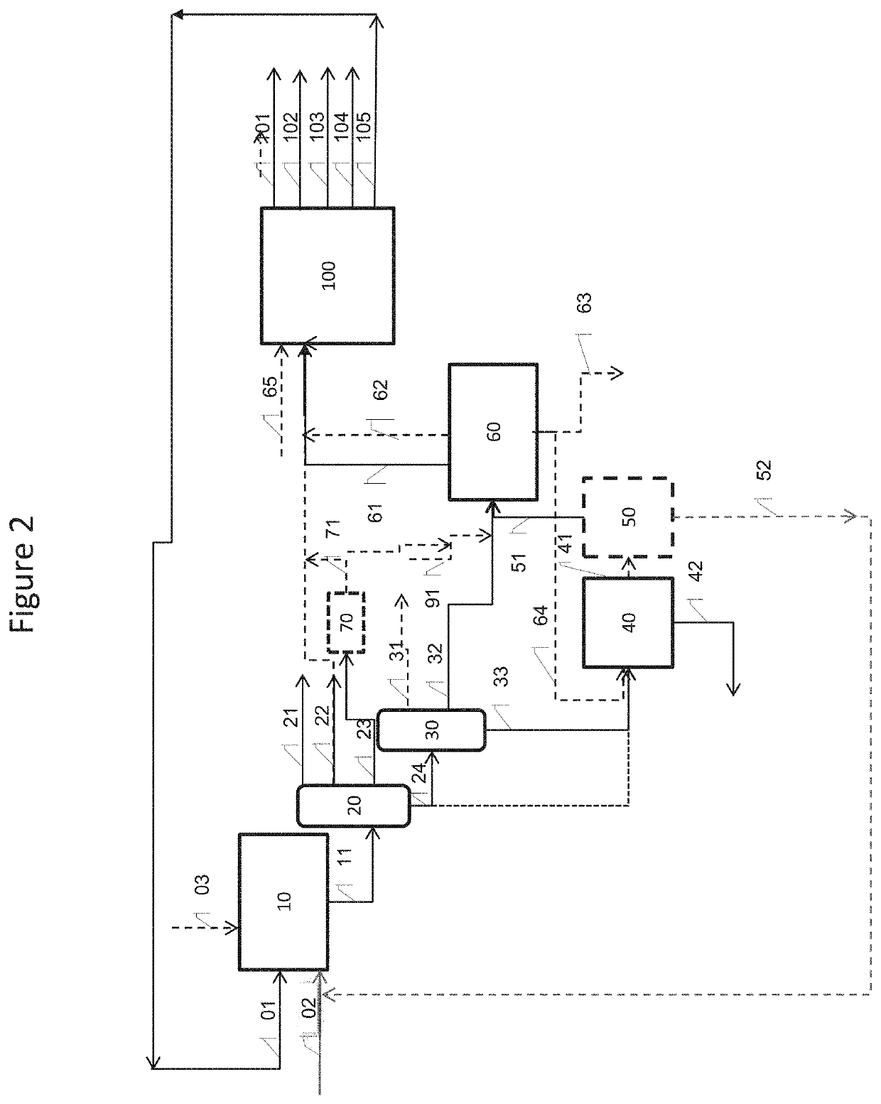
[0238]The feedstocks used in this example are identical to those of Examples 1 and 2. They are used in a process according to one variant of the invention described in FIG. 2.

[0239]The feedstocks are treated in a deep hydroconversion unit 10 as in Example 1, and under the same operating conditions, without addition of catalytic precursor to the feedstock. The two feedstocks are fed separately to the first reactor. The products of the unit are treated in the same fractionation section. The hydrocracking unit 60 and the steam cracking unit 100 are operated by treating the same streams and under the same operating conditions as in Example 2, and produce the same effluents.

[0240]A unit for deasphalting with solvent in two steps (a first step 40 and a second step 50) treats the vacuum residue 33 obtained from the hydroconversion unit 10. The light deasphalted oil fraction 51 produced is sent to the hydrocracking unit 60 as a mixture with the vacuum gas oil fraction 31 and the diesel frac...


PUM

PropertyMeasurementUnit
boiling pointaaaaaaaaaa
feed temperature T2aaaaaaaaaa

Abstract

The invention relates to a process for converting a feedstock comprising pyrolysis oil and a heavy hydrocarbon-based feedstock, with:a) a step of hydroconversion in a reactor;b) a step of separating the liquid effluent obtained from step a) into a naphtha fraction, a gas oil fraction, a vacuum gas oil fraction and an unconverted residue fraction;c) a step of hydrocracking of the vacuum gas oil fraction;d) a step of fractionating the hydrocracked liquid effluent obtained from step c) into a naphtha fraction, a gas oil fraction and a vacuum gas oil fraction;e) a step of steam cracking of a portion of the naphtha fraction obtained from step d);f) a step of fractionating at least a portion of the steam-cracked effluent obtained from step e);g) a step in which the pyrolysis oil fraction obtained from step f) is sent into step a).

Description

TECHNICAL FIELD[0001]The invention relates to the hydroconversion treatment of heavy hydrocarbon feedstocks, including at least one cut obtained from steam cracking.PRIOR ART[0002]The steam cracking of hydrocarbon-based feedstocks leads, in a known manner, to several cuts, of which the heaviest cut derived from the steam cracking unit is known as “pyrolysis oil” (or by its abbreviation “py-oil”).[0003]This cut is usually used as fuel, either internally in the refinery where the steam cracking unit is located, or externally, for example for power generating units, thus solely for the purpose of burning it to recover the combustion heat produced.[0004]This cut contains high-temperature pyrolysis reaction products and in particular “refractory” heavy molecular structures such as “asphaltenes” and “resins”.[0005]“Asphaltenes” constitute a family of compounds that are soluble in aromatic and polyaromatic solvents and insoluble in aliphatic hydrocarbons (n-pentane, n-heptane, etc.). Their...

Claims


Application Information

Patent Timeline
Patent Type & Authority Patents(United States)
IPC IPC(8): C10G69/06C10G9/36C10G21/00C10G45/16C10G47/02
CPCC10G69/06C10G9/36C10G21/003C10G45/16C10G47/02C10G2300/107C10G2300/1077C10G2300/206C10G2300/4081C10G2400/02C10G2400/20C10G69/02C10G65/10C10G2400/04C10G67/02C10G49/02C10G49/002
Inventor FRECON, JACINTHELE BARS, DELPHINENGUYEN, HONG DUC
Owner AXENS SA
Why Eureka
Try Eureka