Laminate, antireflection product, and manufacturing method thereof

a technology of anti-reflection product and manufacturing method, which is applied in the direction of synthetic resin layered products, instruments, optical elements, etc., can solve the problems of complex manufacturing process of anti-reflection layer, high production cost, and high device cost, and achieve satisfactory anti-reflection performance, easy manufacturing of anti-reflection, and low haze

Active Publication Date: 2021-12-28
FUJIFILM CORP
View PDF29 Cites 0 Cited by
  • Summary
  • Abstract
  • Description
  • Claims
  • Application Information

AI Technical Summary

Benefits of technology

[0009]In the technique of JP2009-139796A, it is required to etch a transparent resin with a high frequency plasma device or the like, and thus the manufacturing process of the antireflection layer becomes complicated. Particularly, a plasma treatment of large glass as in a windshield of automobile or the like causes a device to be expensive and production cost to be high.
[0010]An object of the present invention is to provide a laminate that can be used for easily manufacturing an antireflection layer having a satisfactory antireflection performance, low haze, and small muddiness, an antireflection product, a method of manufacturing a laminate, and a method of manufacturing an antireflection product.
[0012]As a method of causing the particles to protrude, a method of adjusting a position of the interface of a layer containing a binder compound by causing the binder compound to permeate the substrate is provided. However, in the case of using the glass substrate as the substrate, permeation of the binder compound into the substrate may not be used, and thus the present inventors have conducted research on lamination of another layer on the coating layer including the composition containing particles and a binder compound and the permeation of the binder compound into the other layer. As a result of diligent research by the present inventors, the present inventors have found that, in a case where a layer including a pressure sensitive adhesive is laminated on a coating layer, a state in which the layer including a pressure sensitive adhesive fixes the particles is maintained, and the binder compound permeates the layer including a pressure sensitive adhesive. The present inventors also have found that it is possible to easily manufacture a satisfactory uneven shape formed by particles even on a glass substrate that the binder compound does not permeate by laminating a layer including a pressure sensitive adhesive on a coating layer, causing an interface between the coating layer and the layer including a pressure sensitive adhesive to come close to the glass substrate side, causing the binder compound to react for curing, and removing the layer including a pressure sensitive adhesive. That is, the present inventors have found that the above object can be achieved by the following means.
[0029]According to the present invention, it is possible to provide a laminate that can be used for easily manufacturing an antireflection product having satisfactory antireflection performance, low haze, and small muddiness, an antireflection product, a method of manufacturing a laminate, and a method of manufacturing an antireflection product.

Problems solved by technology

In the technique of JP2009-139796A, it is required to etch a transparent resin with a high frequency plasma device or the like, and thus the manufacturing process of the antireflection layer becomes complicated.
Particularly, a plasma treatment of large glass as in a windshield of automobile or the like causes a device to be expensive and production cost to be high.
In a case where the particle is exposed to an air interface during the period from coating to curing, the particle easily aggregates, and muddiness is caused in some cases.
Meanwhile, in a case where the protrusion amount of the particles from the layer including the binder is small, sufficient antireflection performance may not be obtained in some cases.

Method used


Image

  • Laminate, antireflection product, and manufacturing method thereof
  • Laminate, antireflection product, and manufacturing method thereof
  • Laminate, antireflection product, and manufacturing method thereof

Examples


example 1

[0366]

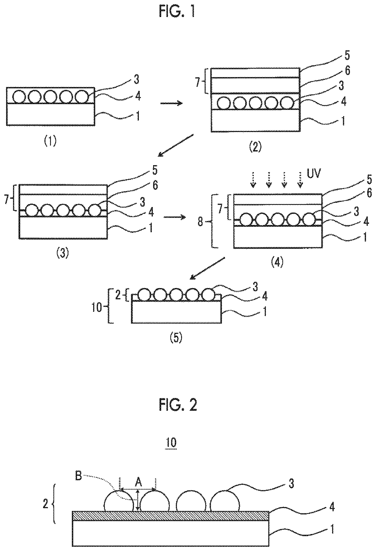
[0367](Step (1): Coating of Layer (a))

[0368]2.8 ml / m2 of the composition (A-1) was coated on the chemical tempered glass substrate with a gravure coater and was dried at 30° C. for 90 seconds. The film thickness of the layer (a) in the step (1) was as provided in Table 1 below.

[0369](Step (1-2): Step of Curing Portion of Curable Compound (a1) in Layer (a) to Obtain Cured Compound (A1c))

[0370]While nitrogen purging was performed so as to be an atmosphere in which an oxygen concentration of 1.5 vol %, irradiation was performed from a surface that is coated with the layer (a) of the glass substrate at an irradiation amount of 5.0 mJ by using a high-pressure mercury lamp (manufactured by Dr. Honle A G, model number: 33351N and Part no.: LAMP-HOZ 200 D24 U 450 E), so as to cure a part of the curable compound (a1). With respect to the measurement of the irradiation amount, HEAD SENSER PD-365 was mounted on an eye ultraviolet ray integrating accumulation light meter UV METER UVPF-A1 ...


PUM

PropertyMeasurementUnit
average primary particle diameteraaaaaaaaaa
thicknessaaaaaaaaaa
softening pointaaaaaaaaaa

Abstract

Provided are a laminate including: a glass substrate; a layer (ca) including a binder; a particle (a2) having an average primary particle diameter of 100 nm to 380 nm; and a layer (b) including a pressure sensitive adhesive, in which the layer (ca) is present on a side closer to the glass substrate than the layer (b), and the particle (a2) is buried in layers obtained by combining the layer (ca) and the layer (b) and protrudes from an interface of the layer (ca) on a side opposite to an interface of the layer (ca) on the glass substrate side, an antireflection product using the laminate, and a method of manufacturing the laminate and an antireflection product.

Description

CROSS-REFERENCE TO RELATED APPLICATIONS[0001]This is a continuation of International Application No. PCT / JP2017 / 27752 filed on Jul. 31, 2017, which was published under Article 21(2) in Japanese, and which claims priority under 35 U.S.C.§ 119(a) from Japanese Patent Application No. 2016-152256 filed on Aug. 2, 2016. The above applications are hereby expressly incorporated by reference, in their entirety, into the present application.BACKGROUND OF THE INVENTION1. Field of the Invention[0002]The present invention relates to a laminate, an antireflection product, and a manufacturing method thereof.2. Description of the Related Art[0003]In an image display device such as a display device using a cathode ray tube (CRT), a plasma display panel (PDP), an electroluminescent display (ELD), a vacuum fluorescent display (VFD), a field emission display (FED), and a liquid crystal display (LCD), it is general to apply an antireflection function in order to prevent decrease in contrast due to refl...

Claims


Application Information

Patent Timeline
Patent Type & Authority Patents(United States)
IPC IPC(8): G02B1/118B32B5/16B32B7/12C03C17/32C03C17/42G02B1/113B32B17/10B32B27/14
CPCG02B1/118B32B5/16B32B7/12B32B17/10018B32B27/14B32B2264/102C03C17/007C03C2217/445C03C2217/478C03C2217/73B32B7/06G02B1/111B32B17/06
Inventor FUKUSHIMA, YUTAIBUKI, SHUNTARO
Owner FUJIFILM CORP
Why Eureka
Try Eureka