Charged particle beam system and method of measuring sample using scanning electron microscope

a scanning electron microscope and particle beam technology, applied in the direction of electric discharge tubes, instruments, measurement devices, etc., can solve the problem that the determination does not take into account the actual three-dimensional shape of the sample, and achieve the effect of avoiding collision of the sample unit with the structure and allowing relatively easy determination

Active Publication Date: 2022-01-04
JEOL LTD
View PDF22 Cites 2 Cited by
  • Summary
  • Abstract
  • Description
  • Claims
  • Application Information

AI Technical Summary

Benefits of technology

[0009]According to the structure described above, the movement of the sample unit can be controlled based on the three-dimensional shape of the sample and the three-dimensional shape of the structure. Thus, for example, when it is expected that the sample unit will move close to or collide with the structure, the movement of the sample unit may be restricted, or a positioning of the sample unit can be optimized. Specifically, it becomes easier to move the sample closer to the objective lens. If the input of the sample height by the user becomes unnecessary, the load of the user can be reduced.
[0011]According to another aspect of the present disclosure, the control means controls the movement of the sample unit in the sample chamber such that the sample unit does not collide with the structure. According to this configuration, the collision of the sample unit with the structure is avoided. The concept of the movement includes a change of a position and a change of an orientation. The three-dimensional shape measurement of the sample may be executed outside of the sample chamber or inside the sample chamber. Alternatively, the three-dimensional shape measurement of the sample may be executed in a space adjacent to the sample chamber.
[0012]According to another aspect of the present disclosure, the control means comprises: simulation means which executes a simulation for virtually trying movement of the sample unit based on movement information of the sample unit prior to movement of the sample unit in the sample chamber; and determining means which determines collision of the sample unit with the structure based on a result of execution of the simulation, and, when the collision is determined, movement of the sample unit is prohibited. According to this configuration, even when the sample unit and the structure have complex forms or even when the movement of the sample unit is complex, the collision can be determined relatively easily. Alternatively, a theoretical collision may be determined in consideration of a certain margin. The concept of the movement information of the sample unit includes movement information of the stage.
[0015]According to another aspect of the present disclosure, a group of ports are provided in the sample chamber, one or a plurality of optional elements are provided on one or a plurality of used ports selected from among the group of ports during use of an optional element, and the structure includes the one or the plurality of optional elements during the use of the optional element. According to the above-described configuration, when one or a plurality of optional elements are used, the second shape data can be generated in consideration of the optional element(s), and the movement of the sample unit can be controlled based thereon. In other words, when the optional element is used, collision of the sample unit with the optional element can be prevented. For example, in the scanning electron microscope system, an X-ray detector, a nozzle, or the like may be exemplified as the optional element.
[0019]According to another aspect of the present disclosure, the imitated image includes a sample unit object corresponding to the sample unit and a structure object corresponding to the structure, and, when collision between the sample unit and the structure is determined prior to the movement of the sample unit, the imitated image generating means reflects a result of the determination in at least one of the sample unit object and the structure object. According to this configuration, a predicted collision can be visually recognized beforehand, and thus, it becomes easier to take a countermeasure for the collision beforehand. For example, the sample may be re-machined, the holder may be exchanged, or an optional detector may be removed, based on a colliding part.

Problems solved by technology

However, this determination does not take into consideration the actual three-dimensional shape of the sample.
According to the related art described above, problems may arise such as occurrence of a collision due to erroneous input of the maximum height, user load involved with the input of the maximum height, and the sample not being moved closer to the objective lens although the situation permits such movement of the sample closer to the objective lens.

Method used


Image

  • Charged particle beam system and method of measuring sample using scanning electron microscope
  • Charged particle beam system and method of measuring sample using scanning electron microscope
  • Charged particle beam system and method of measuring sample using scanning electron microscope

Examples


Embodiment Construction

[0035]An embodiment of the present disclosure will now be described with reference to the drawings.

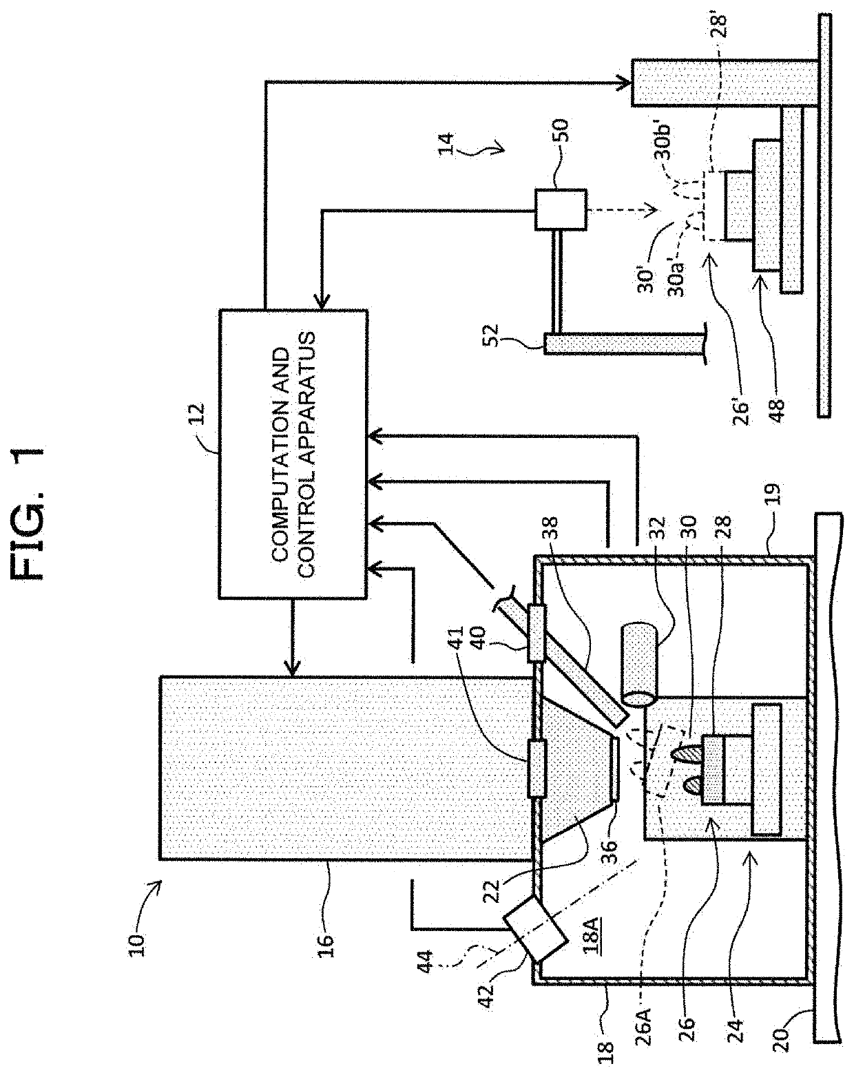
[0036]FIG. 1 shows an example structure of a charged particle beam system according to an embodiment of the present disclosure. In the structure exemplified in the figures, the charged particle beam system is a scanning electron microscope system. Alternatively, the structure described below may be applied to an ion irradiation system or the like.

[0037]The scanning electron microscope system is a system for measuring and observing a sample using an electron beam. In the structure exemplified in the figures, the scanning electron microscope system comprises a scanning electron microscope 10, a computation and control apparatus 12, and a shape measurement apparatus 14. The scanning electron microscope 10 serving as a measurement unit and the computation and control apparatus 12 serving as an information processor correspond to a scanning electron microscope apparatus. The computation and...


PUM


Abstract

First shape data representing a three-dimensional shape of a sample unit including a sample is generated based on a result of three-dimensional shape measurement of the sample. Second shape data representing a three-dimensional shape of a structure which exists in a sample chamber is generated. Movement of the sample unit is controlled based on the first shape data and the second shape data such that collision of the sample unit with the structure does not occur.

Description

CROSS REFERENCE TO RELATED APPLICATION[0001]This application claims priority to Japanese Patent Application No. 2019-017034 filed Feb. 1, 2019, the disclosure of which is hereby incorporated by reference in its entirety.BACKGROUND OF THE INVENTIONField of the Invention[0002]The present disclosure relates to a charged particle beam system and a method of measuring a sample using a scanning electron microscope, and in particular to control of movement of a sample in a sample chamber.Description of Related Art[0003]A charged particle beam system is a system which measures a sample using charged particles such as electrons and ions. As a typical system, there is known a scanning electron microscope system. The scanning electron microscope system is formed as a single entity of a scanning electron microscope apparatus or as a combination of the scanning electron microscope apparatus and other apparatuses.[0004]In the scanning electron microscope apparatus, prior to observation of a sampl...

Claims


Application Information

Patent Timeline
Patent Type & Authority Patents(United States)
IPC IPC(8): H01J37/22H01J37/20H01J37/28
CPCH01J37/20H01J37/222H01J37/226H01J37/28H01J2237/2007H01J2237/20285H01J2237/221H01J2237/226H01J2237/24578H01J37/265G01N23/2204G01B15/04G01N2223/07G01N2223/102G01N2223/309H01J2237/20292
Inventor NEMOTO, YOSHIKAZUMURAKAMI, YUTAMAEDA, TAKAKUNIABE, AKIRAKAWAMOTO, MASATSUGUMEZAKI, HIROKI
Owner JEOL LTD
Why Eureka
Try Eureka