
Nitride semiconductor ultraviolet light-emitting element

a technology of ultraviolet light and semiconductor, applied in the direction of basic electric elements, semiconductor devices, electrical equipment, etc., can solve the problem of not being able to effectively extract the outside of the element, and achieve the effect of improving the efficiency of wall plugs and improving internal quantum efficiency

Active Publication Date: 2022-01-04
NIKKISO COMPANY
View PDF20 Cites 2 Cited by
  • Summary
  • Abstract
  • Description
  • Claims
  • Application Information

AI Technical Summary

Benefits of technology

[0053]According to the nitride semiconductor ultraviolet light-emitting element of the above-described features, as a plurality of Ga-rich layers is formed in the n-type layer, an improvement in the wall plug efficiency due to an improvement in the internal quantum efficiency Ein or the voltage efficiency Ev or both is expected.

Problems solved by technology

However, since the p-type nitride semiconductor layer of a high AlN molar fraction is difficult to form a good ohmic contact with the p-electrode, it is generally performed to form a p-type contact layer made of a p-type AlGaN semiconductor with a low AlN molar fraction (specifically p-GaN), which can have a good ohmic contact with the p-electrode, to the uppermost layer of the p-type nitride semiconductor layer.
Since the AlN molar fraction of the p-type contact layer is smaller than that of the AlGaN-based semiconductor constituting the active layer, ultraviolet light emitted toward the p-type nitride semiconductor layer side from the active layer is absorbed in the p-type contact layer, and cannot be effectively extracted to the outside of the element.

Method used


Image

  • Nitride semiconductor ultraviolet light-emitting element
  • Nitride semiconductor ultraviolet light-emitting element
  • Nitride semiconductor ultraviolet light-emitting element

Examples


Embodiment Construction

[0062]A nitride semiconductor ultraviolet light-emitting element (hereinafter, simply referred to as a “light-emitting element”) according to an embodiment of the present invention will be described with reference to the drawings. Incidentally, in the drawings used in the following description (except for HAADF-STEM images), the dimensional ratios of each part are not necessarily the same as those of the actual elements because the essential part is emphasized to schematically show the invention for ease of understanding of the description. Hereinafter, in the present embodiment, description will be made on the assumption that the light-emitting element is a light-emitting diode.

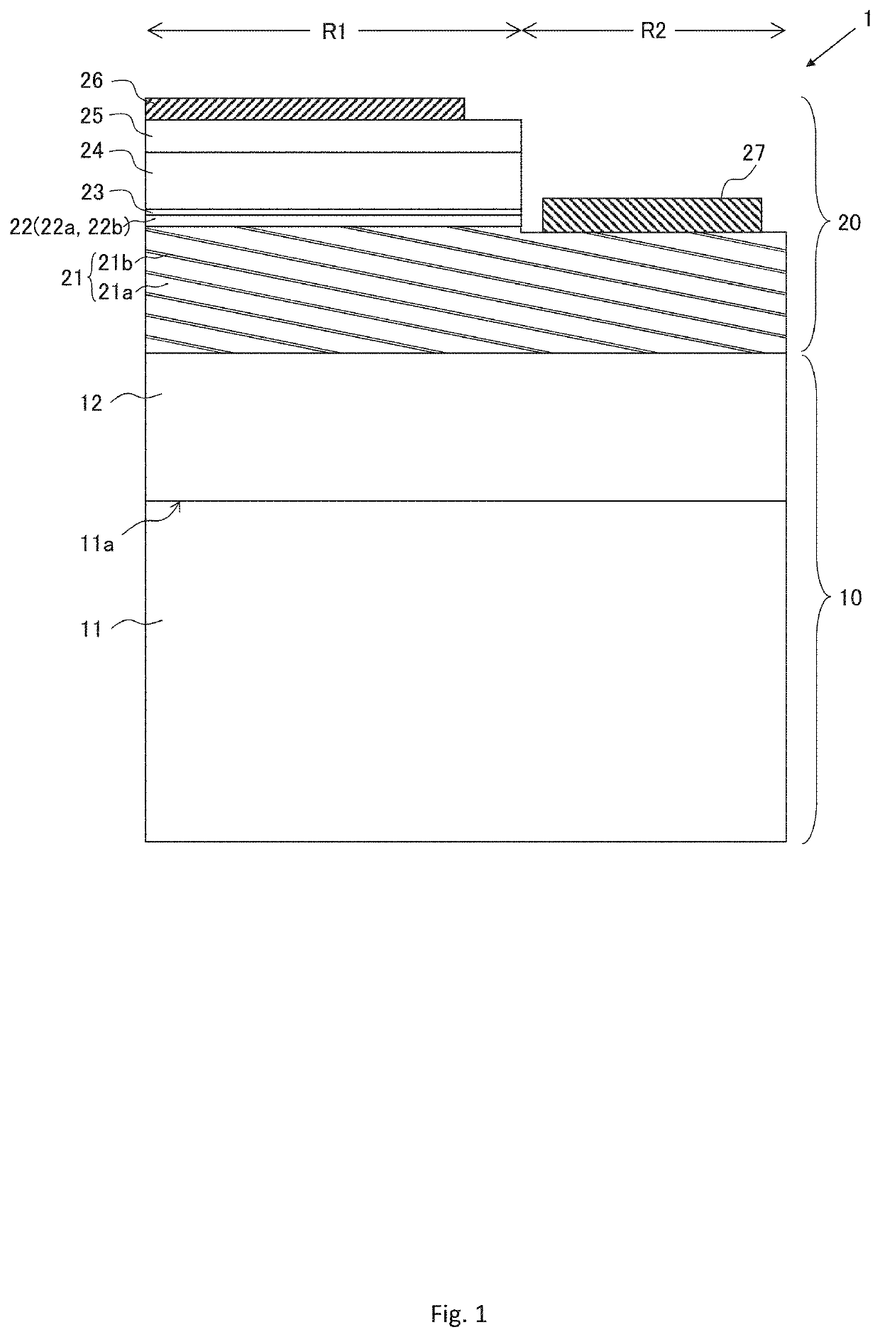
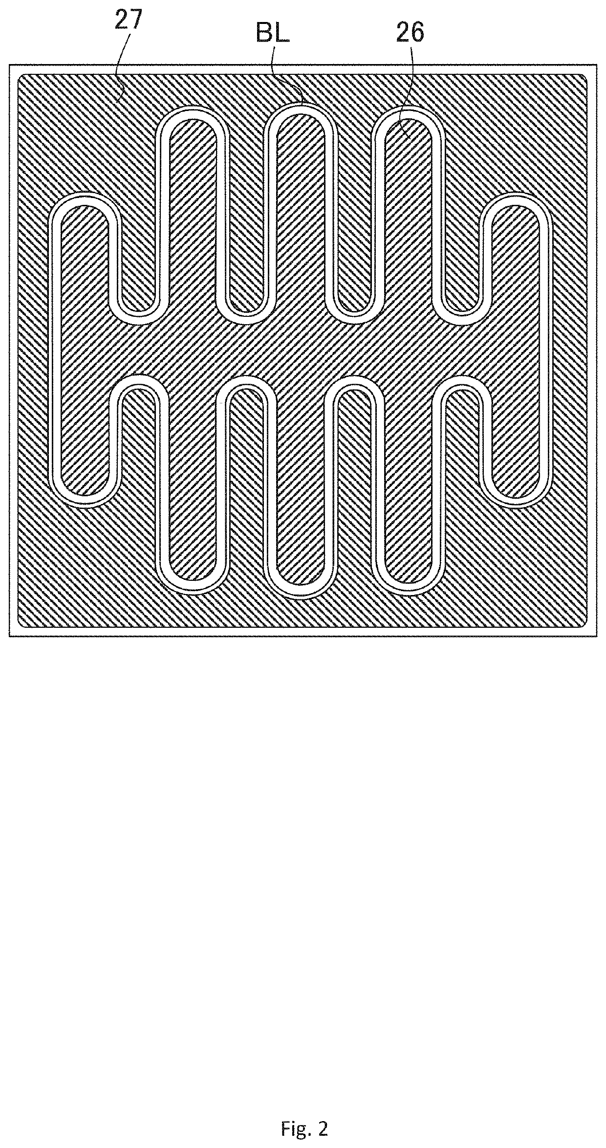
[0063]As shown in FIG. 1, the light-emitting element 1 of the present embodiment includes an underlying part 10 including a sapphire substrate 11, and a light-emitting element structure part 20 including a plurality of AlGaN-based semiconductor layers 21-25, a p-electrode 26, and an n-electrode 27. The nitri...


PUM

PropertyMeasurementUnit
thicknessaaaaaaaaaa
vertical separation distanceaaaaaaaaaa
inclination angleaaaaaaaaaa

Abstract

To improve a wall plug efficiency in a nitride semiconductor light-emitting element for extracting ultraviolet light emitted from an active layer toward an n-type nitride semiconductor layer side to outside of the element. In the n-type AlGaN-based semiconductor layer 21 constituting the nitride semiconductor light-emitting element 1, a plurality of thin film-like Ga-rich layers that is a part of the n-type layer 21 having a locally high Ga composition ratio exists spaced apart from each other in a vertical direction that is orthogonal to the upper surface of the n-type layer 21, an extending direction of at least a part of the plurality of Ga-rich layers on a first plane parallel to the vertical direction is inclined with respect to an intersection line between the upper surface of the n-type layer and the first plane, the plurality of Ga-rich layers exists in stripes on the second plane parallel to the upper surface of the n-type layer 21 in an upper layer region having a thickness of 100 nm or less at lower side from the upper surface of the n-type layer 21, AlN molar fractions of the Ga-rich layers 21b are greater than AlN molar fraction of a well layer 22b in an active layer 22 constituting the light-emitting element 1.

Description

TECHNICAL FIELD[0001]The present invention relates to a nitride semiconductor ultraviolet light-emitting element having a light emitting layer made of an AlGaN-based semiconductor.BACKGROUND ART[0002]In general, there are a lot of nitride semiconductor light-emitting elements with a light-emitting element structure comprising a plurality of nitride semiconductor layers formed by epitaxial growth on a substrate such as sapphire. A nitride semiconductor layer is represented by the general formula: Al1-x-yGaxInyN (0≤x≤1, 0≤y≤1, 0≤x+y≤1).[0003]The light-emitting element structure of a light-emitting diode has a double hetero structure in which an active layer made of a nitride semiconductor layer having a single-quantum-well structure (SQW) or a multi-quantum-well structure (MQW) is sandwiched between an n-type nitride semiconductor layer and a p-type nitride semiconductor layer. When the active layer is an AlGaN-based semiconductor layer, by adjusting an AlN molar fraction (also referr...

Claims


Application Information

Patent Timeline
Patent Type & Authority Patents(United States)
IPC IPC(8): H01L33/32H01L33/06H01L33/00
CPCH01L33/32H01L33/007H01L33/0075H01L33/06H01L33/14H01L33/025
Inventor HIRANO, AKIRANAGASAWA, YOSUKECHICHIBU, SHIGEFUSAKOJIMA, KAZUNOBU
Owner NIKKISO COMPANY
Learn More