
Electronic component, antenna and RF tag

a technology of electronic components and antennas, applied in loop antennas with ferromagnetic cores, instruments, inductances, etc., can solve problems such as loss of sensitivity of antennas, and achieve the effects of improving communication sensitivity, sufficient communication distance, and excellent characteristics

Active Publication Date: 2022-01-18
TODA IND
View PDF9 Cites 0 Cited by
  • Summary
  • Abstract
  • Description
  • Claims
  • Application Information

AI Technical Summary

Benefits of technology

The present invention is an electronic component that is excellent at high frequencies, specifically in the 13.56 MHz range. It can be used as an antenna for RFID applications and is highly sensitive, allowing for long distance communication. Despite its small size, the antenna maintains sufficient communication distance even when placed near metal components. This allows for its use in various applications without limitation on installation space.

Problems solved by technology

However, such an antenna having a planar shape requires not only a large installation area, but also poses such a problem that if any metal material approaches to the antenna, an image having an opposite phase to that of the antenna is produced on the metal material, so that the antenna loses its sensitivity.

Method used

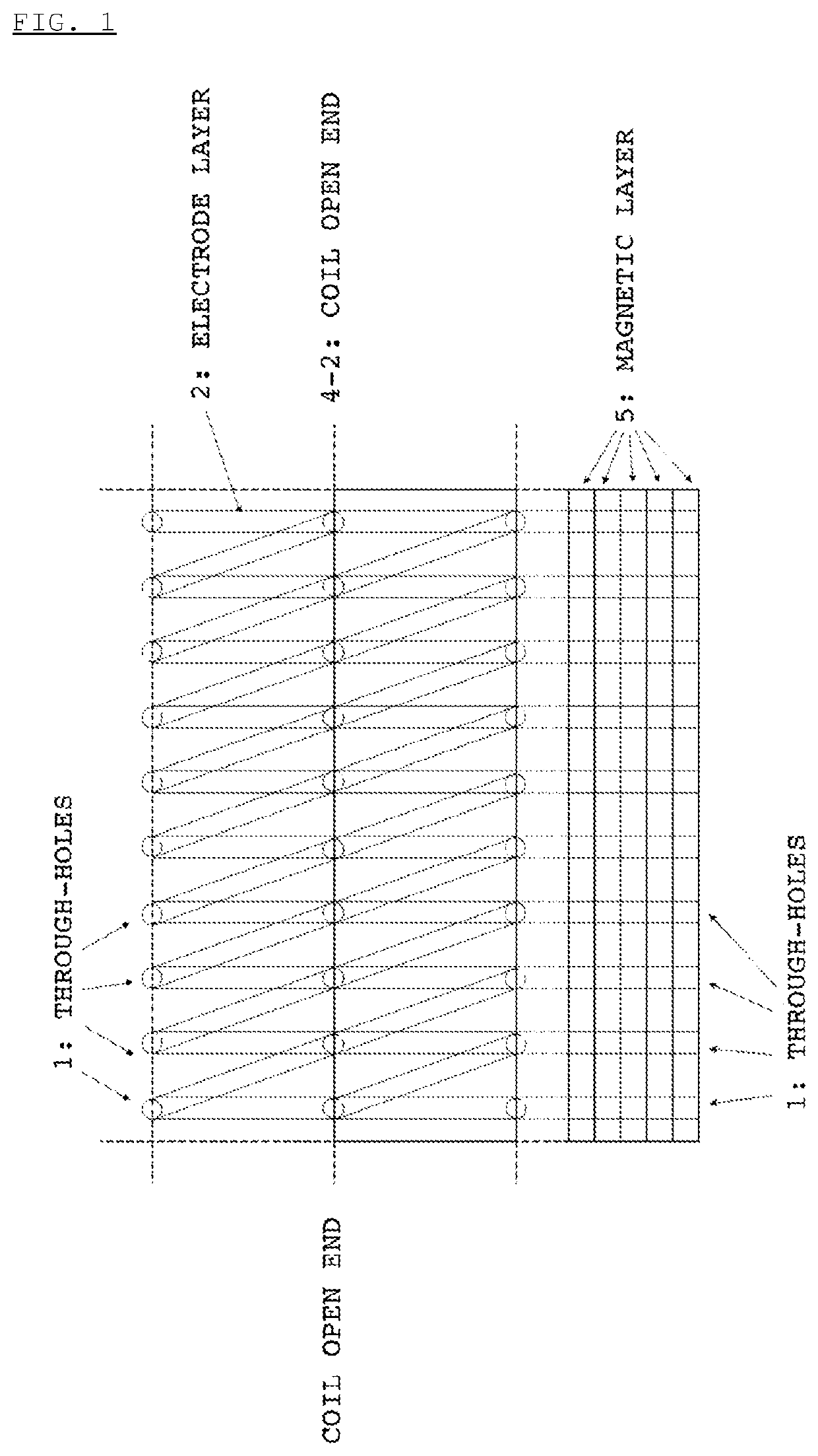
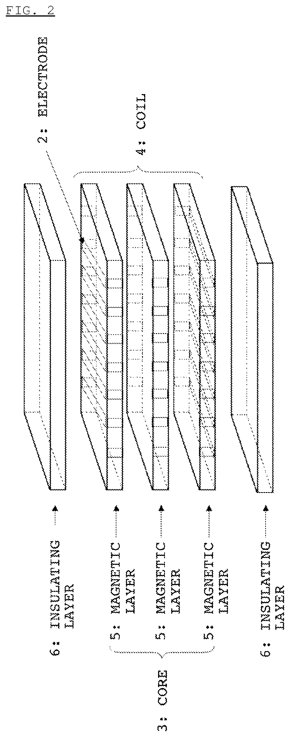
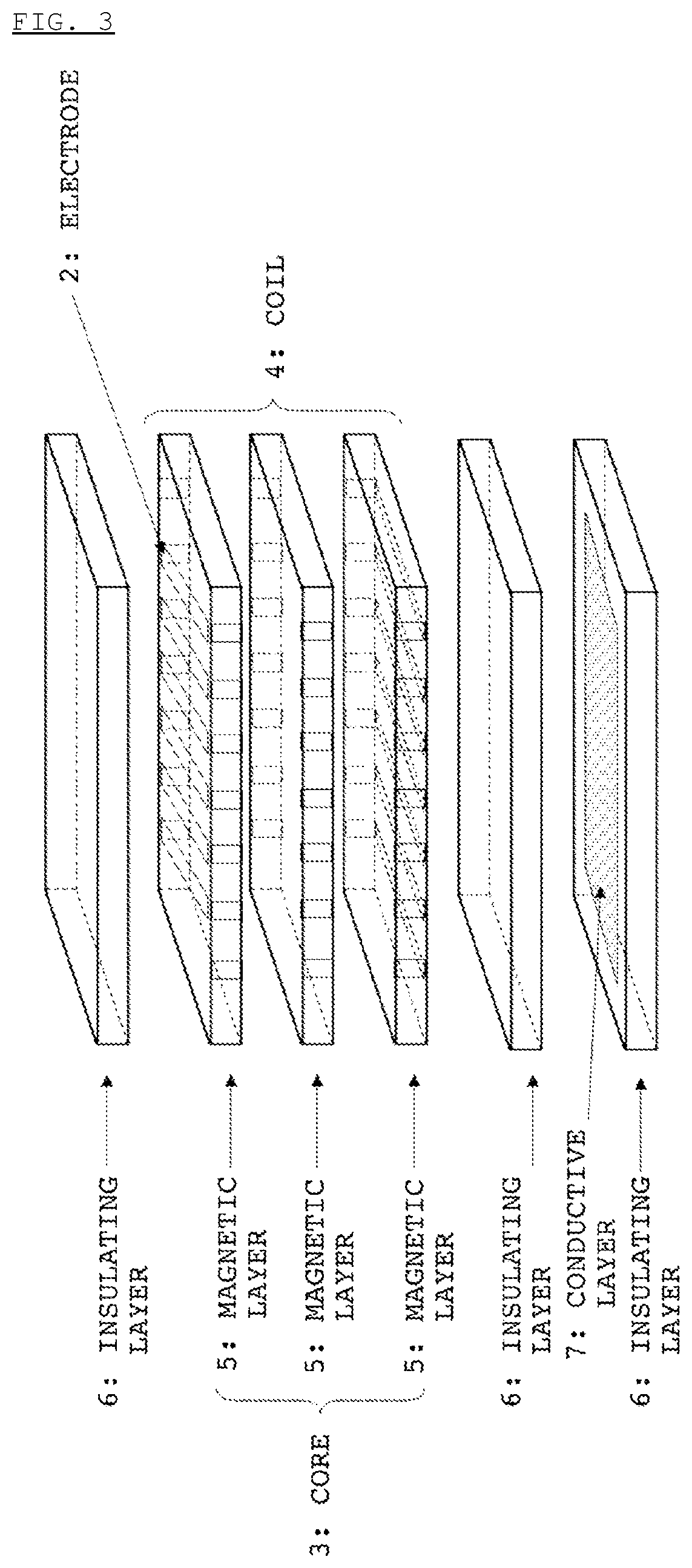

Image

  • Electronic component, antenna and RF tag
  • Electronic component, antenna and RF tag
  • Electronic component, antenna and RF tag

Examples


example 1

[0080]One hundred parts by weight of Ni—Zn—Cu ferrite calcined particles (Fe2O3: 48.59 mol %; NiO: 24.82 mol %; ZnO: 15.95 mol %; CuO: 10.37 mol %), 8 parts by weight of a butyral resin, 5 parts by weight of a plasticizer and 80 parts by weight of a solvent were mixed in a ball mill to prepare a slurry. The resulting slurry was applied on a PET film by a doctor blade to form a coating layer with a size of 150 mm square such that the thickness of the coating layer was 0.1 mm upon being sintered to form a molded sheet, thereby obtaining a green sheet for a magnetic layer (5). The thus obtained green sheet was sintered at a sintering temperature of 900° C. to obtain a ferrite core. The magnetic characteristics of the thus obtained ferrite core are shown in Table 1.

[0081]In addition, 100 parts by weight of Zn—Cu ferrite calcined particles (Fe2O3: 46.5 mol %; ZnO: 42.0 mol %; CuO: 11.5 mol %), 8 parts by weight of a butyral resin, 5 parts by weight of a plasticizer and 80 parts by weight...

example 2

[0087]The same procedure as in Example 1 was conducted except that the composition of the Ni—Zn—Cu ferrite calcined particles used for forming the magnetic layer was changed to the composition comprising 48.31 mol % of Fe2O3, 21.93 mol % of NiO, 19.18 mol % of ZnO, 10.29 mol % of CuO and 0.29 mol % of CoO, thereby manufacturing an antenna.

example 3

[0088]The same procedure as in Example 1 was conducted except that the composition of the Ni—Zn—Cu ferrite calcined particles used for forming the magnetic layer was changed to the composition comprising 48.65 mol % of Fe2O3, 24.76 mol % of NiO, 16.10 mol % of ZnO, 10.35 mol % of CuO and 0.14 mol % of CoO, thereby manufacturing an antenna.


PUM

PropertyMeasurementUnit
molar ratioaaaaaaaaaa

Abstract

The present invention relates to an electronic component, and also relates to an antenna for information communication using a magnetic field component, which is capable of satisfying both of downsizing and improvement in communication sensitivity. The electronic component of the present invention comprises a ferrite core and a coil, in which a ferrite constituting the ferrite core has a spinel structure and comprises Fe, Ni, Zn, Cu and Co as constitutional metal elements, and when contents of the respective constitutional metal elements in the ferrite are calculated in terms of Fe2O3, NiO, ZnO, CuO and CoO, contents of Fe2O3, NiO, ZnO, CuO and CoO in the ferrite are 46 to 50 mol %, 20 to 27 mol %, 15 to 22 mol %, 9 to 11 mol % and 0.01 to 1.0 mol %, respectively, based on a total content of Fe2O3, NiO, ZnO, CuO and CoO.

Description

[0001]This application is the U.S. national phase of International Application No. PCT / JP2018 / 002660 filed 29 Jan. 2018, which designated the U.S. and claims priority to JP Patent Application No. 2017-015132 filed 31 Jan. 2017, the entire contents of each of which are hereby incorporated by reference.TECHNICAL FIELD[0002]The present invention relates to an electronic component having enhanced operability at a high frequency, and also relates to an antenna for information communication using a magnetic field component. The antenna according to the present invention is capable of satisfying both of downsizing and improvement in communication sensitivity.BACKGROUND ART[0003]With the recent progress of reduction in size and weight of domestic and industrial electronic equipments, etc., there is an increasing need for electronic components used in the aforementioned various electronic equipments which have a reduced size and can be operated with a still higher efficiency and at a still h...

Claims


Application Information

Patent Timeline
Patent Type & Authority Patents(United States)
IPC IPC(8): H01Q7/06G06K19/077H01Q1/22
CPCH01Q7/06G06K19/07775H01Q1/2208H01Q1/2283H01F1/34H01F17/00H01F17/04G06K19/07773
Inventor NOMURA, SATOSHIKOUJIMA, JUNNISHIO, YASUSHINAKATSUKASA, MANATOFUJII, YASUHIKO
Owner TODA IND
Learn More