
System and method for fusion of sacroiliac joint

a sacroiliac joint and fusion technology, applied in the field of bone fusion tools and techniques, can solve the problems of large pre- and post-operative portions, insufficient use of natural live bone tissue, and inability to fully utilize the natural live bone tissue of autografts, etc., to achieve the effect of increasing surgery time, enhancing bone growth characteristics, and improving growth promotion

Active Publication Date: 2022-03-15
ADVANCE RES SYST LLC
View PDF46 Cites 2 Cited by
  • Summary
  • Abstract
  • Description
  • Claims
  • Application Information

AI Technical Summary

Benefits of technology

The implant system described in this patent is designed to improve surgery outcomes and reduce the duration of surgery. It involves a bone screw that acts as a pre-drill, allowing for easier placement without the need for additional drilling. The bone screw has a spongy, compliant nature that helps to compress the bone and prevent displacement or stripping of the screw. The system also allows for the selective deployment of blades to remove material at selected depths and distribute bone grafting material. Overall, the system simplifies the surgical procedure and enhances the growth of bone tissue.

Problems solved by technology

There are certain disadvantages that are inherent to the conventional method described above.
The threads implanted by the conventional method described above may be readily stripped from such tissue, which can negate the benefit of the implant.
Second, such conventional procedures remove large portions of the pre-drilled bone.
As such, conventional procedures do not take full advantage of natural live autograft bone tissue, which is a better growth-promoting substance than other options, such as allograft, synthetic biologic, or xenograft biologic.

Method used


Image

  • System and method for fusion of sacroiliac joint
  • System and method for fusion of sacroiliac joint
  • System and method for fusion of sacroiliac joint

Examples


Embodiment Construction

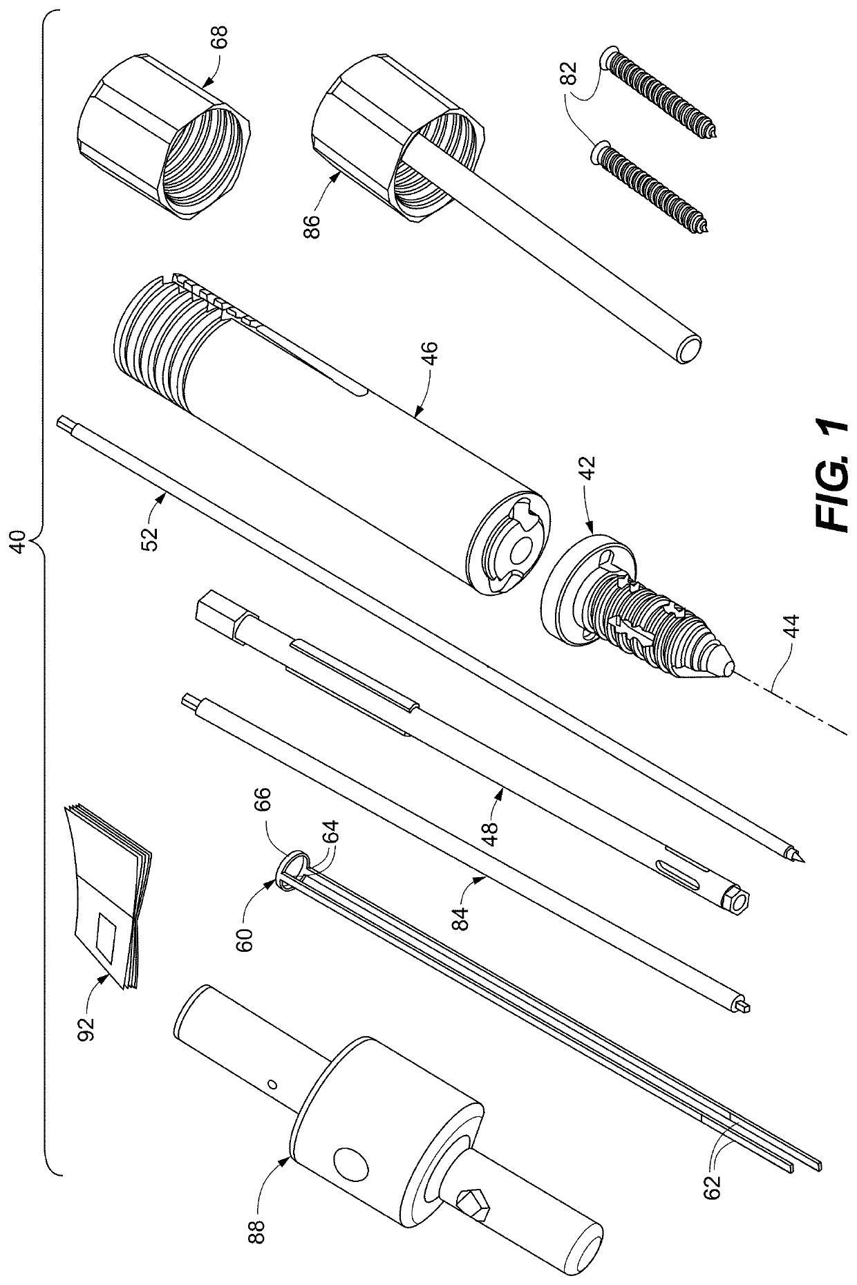
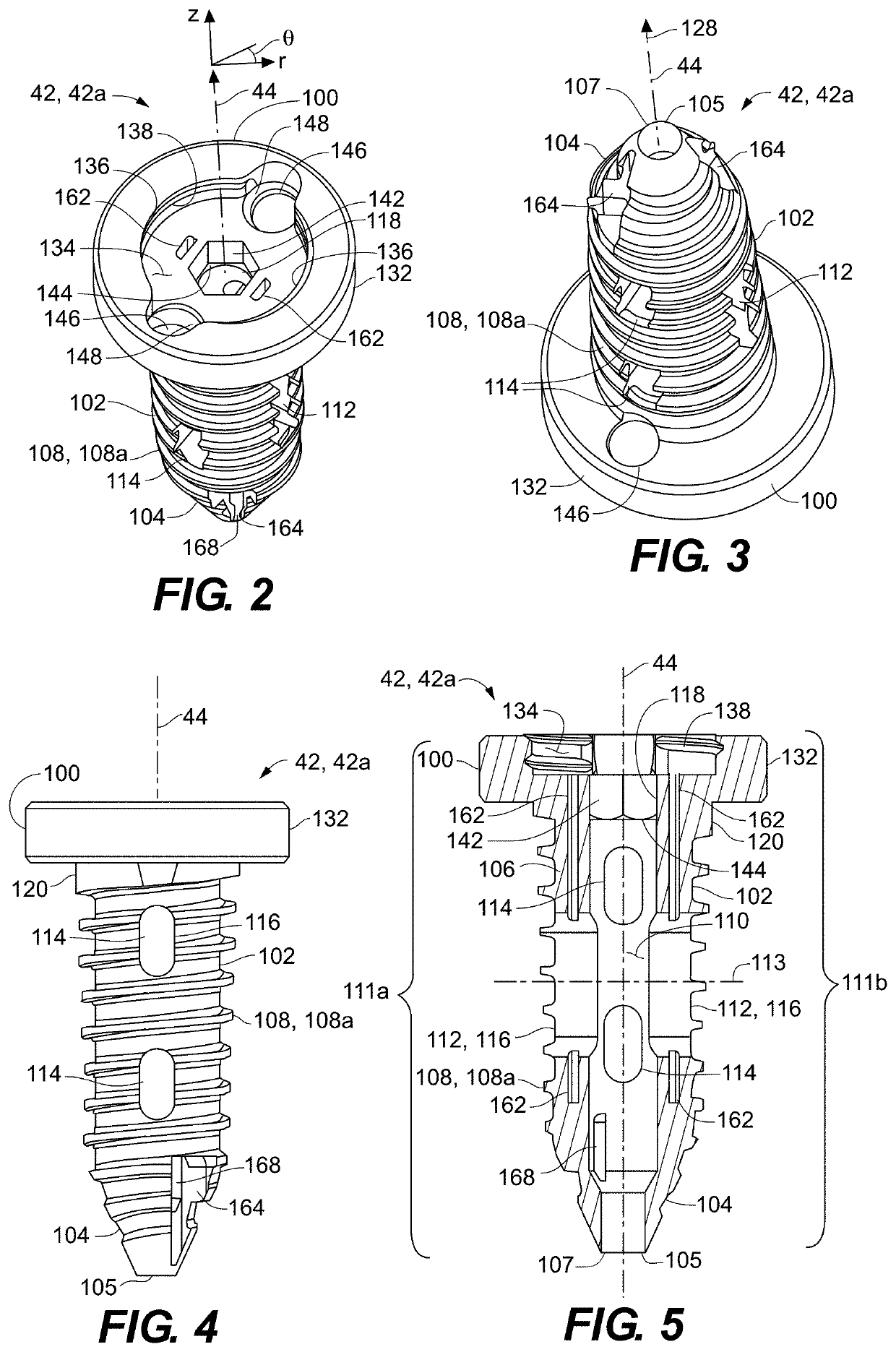
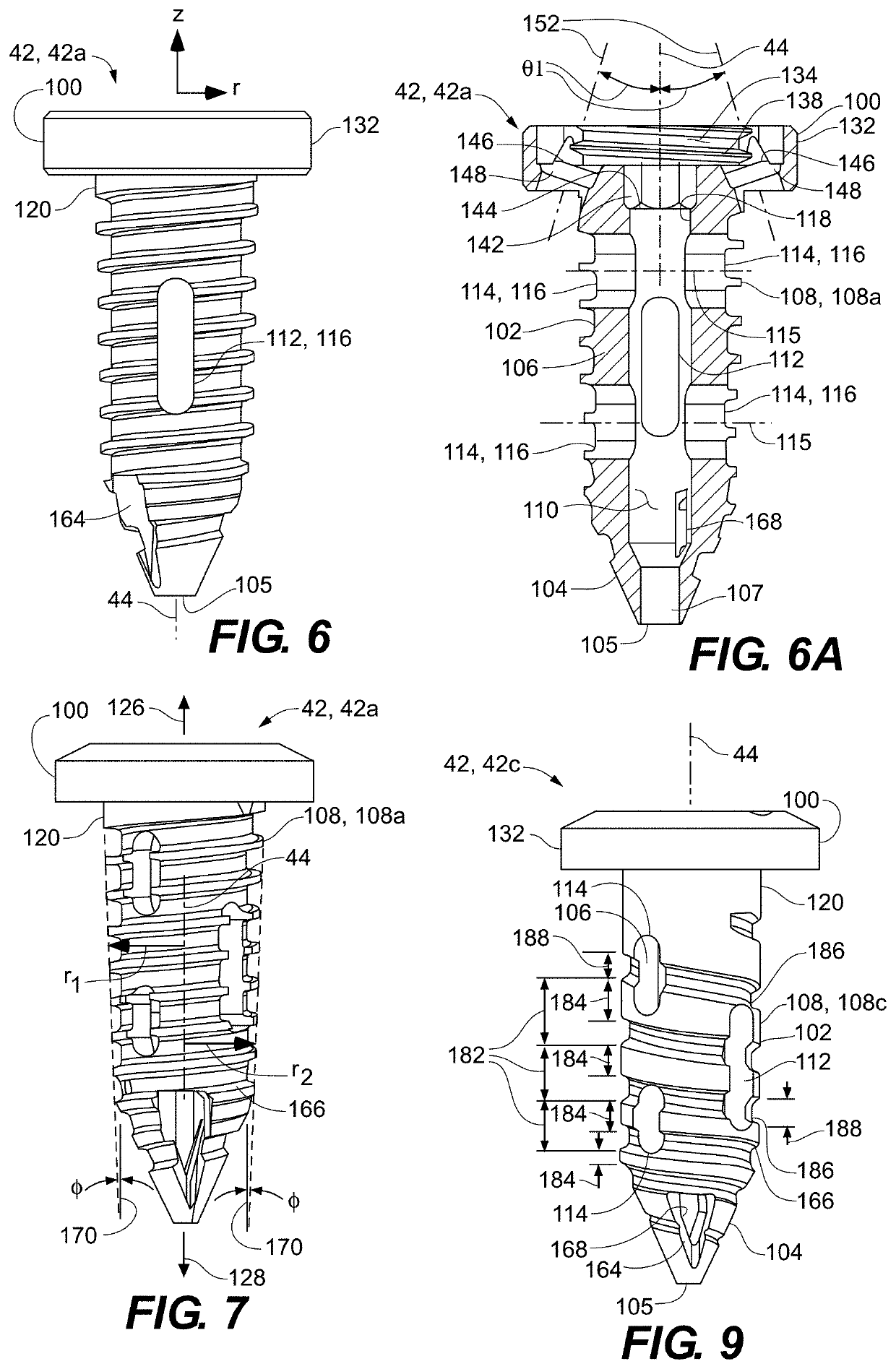
[0094]Referring to FIG. 1, an implant system 40 for fusion of a sacroiliac joint is depicted according to an embodiment of the disclosure. The implant system 40 includes a main or primary screw 42 that defines a central axis 44 about which the primary screw 42 rotates, the primary screw 42 being configured to detachably mate with an inserter 46. In some embodiments, a main or primary screw driver 48 is configured to access the primary screw 42 through the inserter 46. The primary screw 42, the inserter 46, and the primary screw driver 48 may be configured for sliding over a guide wire or rod 52. The implant system 40 includes a blade assembly 60 including a pair of flexible, elongate blades 62 having proximal ends 64 that are joined to a ring 66. A drive cap 68 may also be included for deployment of the elongate blades 62. The implant system 40 may include one or more side screws 82 for anchoring the primary screw 42, a side screw driver 84 for setting the side screw(s) 82, a plunge...


PUM


Abstract

A system for performing a minimally invasive sacroiliac joint fusion. The system may be in the form of a disposable kit, with the components streamlined so that the procedure can be performed in a few minutes. The screw components are self-drilling and self-tapping. The system may deploy blades through the walls of the primary screw which cut away material as the primary screw is set, for denuding the sacroiliac joint. The primary screw is designed bore through and internalize bone tissue in an autografting process. The implant system may include components for packing bone grafting material into the screw to supplement autograft bone tissue internalized in the primary screw during placement. At least one side screw is passed through a head of the primary screw to anchor the head and prevent it from backing out after implantation.

Description

RELATED APPLICATIONS[0001]This application claims the benefit of U.S. Provisional Patent Application No. 62 / 685,605, filed Jun. 15, 2018, U.S. Provisional Patent Application No. 62 / 801,316, filed Feb. 2, 2019, and U.S. Provisional Patent Application No. 62 / 861,937, filed Jun. 14, 2019, the disclosures of which are incorporated by reference herein in their entirety.FIELD OF THE DISCLOSURE[0002]The present disclosure is directed generally to tools and techniques for bone fusion, and more specifically to apparatuses and methods for fusion of a sacroiliac joint.BACKGROUND OF THE DISCLOSURE[0003]Products and techniques for fusion of sacroiliac joints are known. Many techniques involve the implantation of a bone screw that extends substantially perpendicular to the joint. Conventional implantation techniques may require about an hour of surgery to perform. Also, the implants have been known to fail, requiring removal of the implanted bone screw and redress of the joint, at considerable co...

Claims


Application Information

Patent Timeline
IPC IPC(8): A61B17/86A61B17/70A61F2/30A61B17/88A61B34/20A61B6/00A61F2/46A61B17/56
CPCA61F2/30988A61B6/505A61B17/7055A61B17/864A61B17/8615A61B17/8888A61B34/20A61B17/8605A61B17/869A61B17/8685A61B2017/564A61B2017/8655A61F2/4601A61F2/4603A61F2002/30405A61F2002/30593A61F2002/30622A61F2002/30769A61F2002/30777A61F2002/30785A61F2002/30858A61F2002/30995A61B17/7082A61B17/8052A61B17/7098A61B17/1757A61B17/848A61B17/8875A61B2017/0046A61B17/863A61B6/12
Inventor ABBASI, HAMID R.
Owner ADVANCE RES SYST LLC
Learn More