Spent nuclear fuel canister

a nuclear fuel and canister technology, applied in the direction of nuclear engineering, portable shielded containers, etc., can solve the problems of insufficient inability to meet the needs of lubricant management, and difficult access to stored fuel, so as to increase the heat rejection capability of canisters, reduce the risk of human effort and radiation exposure, and safeguard the effect of structural integrity

Active Publication Date: 2022-03-29
HOLTEC INT
View PDF19 Cites 0 Cited by
  • Summary
  • Abstract
  • Description
  • Claims
  • Application Information

AI Technical Summary

Benefits of technology

[0006]To overcome the foregoing limitations in the art for retrieving the spent nuclear fuel (SNF) contents from “all-welded” fuel canister constructions presently used in the nuclear industry, a new and improved spent nuclear fuel canister is disclosed herein which not only maintains the essential features of the canister's structural ruggedness for protecting the fuel, but also makes the fuel more readily accessible without the foregoing cutting process, and with minimum human effort and radiation exposure to the workers. Some embodiments further include heat dissipation features for significantly increasing the heat rejection capability of the canisters, thereby safeguarding the structural integrity of the SNF stored therein. Also importantly, the SNF canisters disclosed herein advantageously maintain the same preferred small dimensions and profile (i.e. height and diameter) of prior canisters with seal welded lids, thereby allowing the new canisters to be used interchangeably in existing outer transport and storage overpacks or casks without modification.
[0007]The SNF canister according to the present disclosure includes a multi-thickness shell and compact bolted closure lid-to-shell joint for ready access to the fuel contents inside. This eliminates the time-consuming and cumbersome prior cutting processes described above which are required to sever a welded joint between the lid and shell in welded lid designs. In one embodiment, the present lid may be directly bolted to the top of the shell.
[0008]To accommodate the bolting and seals required, a multi-thickness shell is provided having a top fastening portion that comprises a reinforcement structure in the form of an annular mounting boss integrally formed with the shell. The top fastening portion of the shell has a greater transverse wall thickness than the wall portion of the shell below, thereby providing additional purchase for engaging the bolts at the bolted lid joint. In some embodiments, the mounting boss may have a wall thickness equal to or greater than at least twice the thickness of the lower shell wall.
[0011]The closure lid has an annular mounting flange receiving the through bolts. The flange is seated on the top end of canister shell. Significantly, the mounting flange does not protrude radially beyond the outer surface of the either the upper fastening portion or lower portions shell to minimize the outside diameter of the canister necessary for storing the canister inside the an outer radiation shielded overpack or cask for transport / storage. This unique lid and bolting construction and arrangement advantageously results in a compact lid design, thereby keeping the outer cask's outside diameter to the smallest possible which is an essential part of a design that complies with the NRC's 10CFR71 regulations. Although bolted lids may be used in the bulker radiation shielded outer transport / storage casks, such bulkier designs are not suit for the inner SNF canister which must maintain the smallest outer diameter and profile possible without substantially reducing the number of spent fuel assemblies which be storage inside the canister.
[0012]In one embodiment, the canister may further comprise a plurality of radial cooling fins arranged perimetrically on the outer surface of the shell to enhance heat dissipation. The fins may be welded directly to the outer surface of the shell or may be integrally formed therewith to provide direct contact. This ensures an effective conductive heat transfer path from the shell to the outer environment surrounding the canister, thereby allowing the fins to act as heat radiators. In some constructions, the fins may be disposed in an annular 360 degree recessed lower area of the outer shell formed by the mounting boss. By locating the fins in the recessed area below the mounting boss, the fins advantageously do not protrude radially outwards beyond the lid, shell, and bottom baseplate of the canister in some implementations to maintain the desired small outside diameter of the canister package, and importantly to protect the fins from damage when handling and moving the canister during the spent fuel dewaters, staging, and transport operations.

Problems solved by technology

The all-welded canister provides guaranteed confinement of the contents, but makes the stored fuel difficult-to-access if repackaging is required at a later date.
While lid cutting tools to sever the lid from the canister shell have been successfully developed and demonstrated, the cutting operation is inherently dose-accretive, cumbersome, and time-consuming requiring metal chip and lubricant management during the process.

Method used


Image

  • Spent nuclear fuel canister
  • Spent nuclear fuel canister
  • Spent nuclear fuel canister

Examples


first embodiment

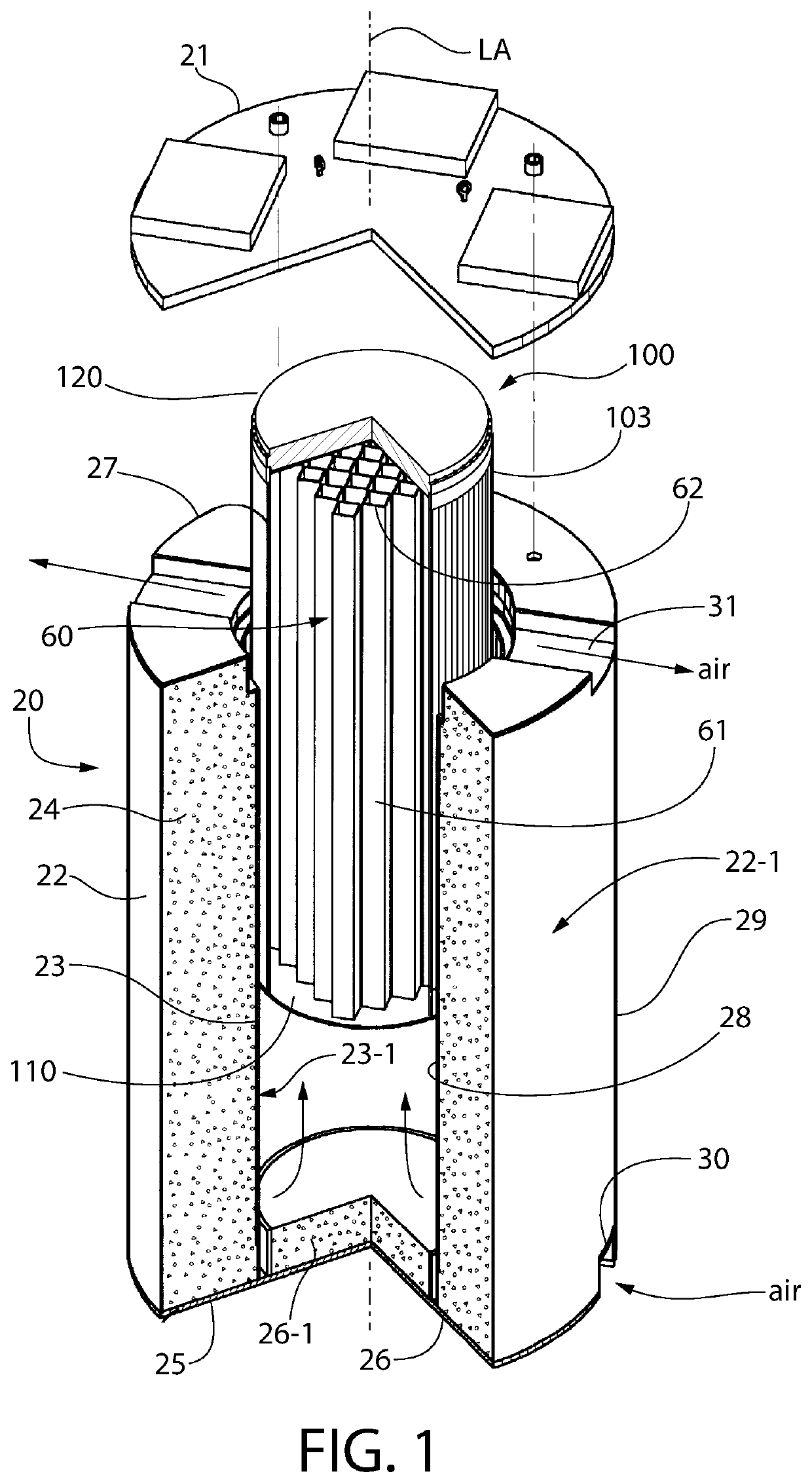
[0051]FIGS. 1-14 depict spent fuel canister 100 with compact bolted lid according to the present disclosure in further detail. The present canister advantageously comprises a bolted joint between the removable top closure lid and the canister body as previously described herein, thereby advantageously providing ready access to the SNF therein for repackaging or other purposes. The bolted lid joint is further described in the discussion which follows.

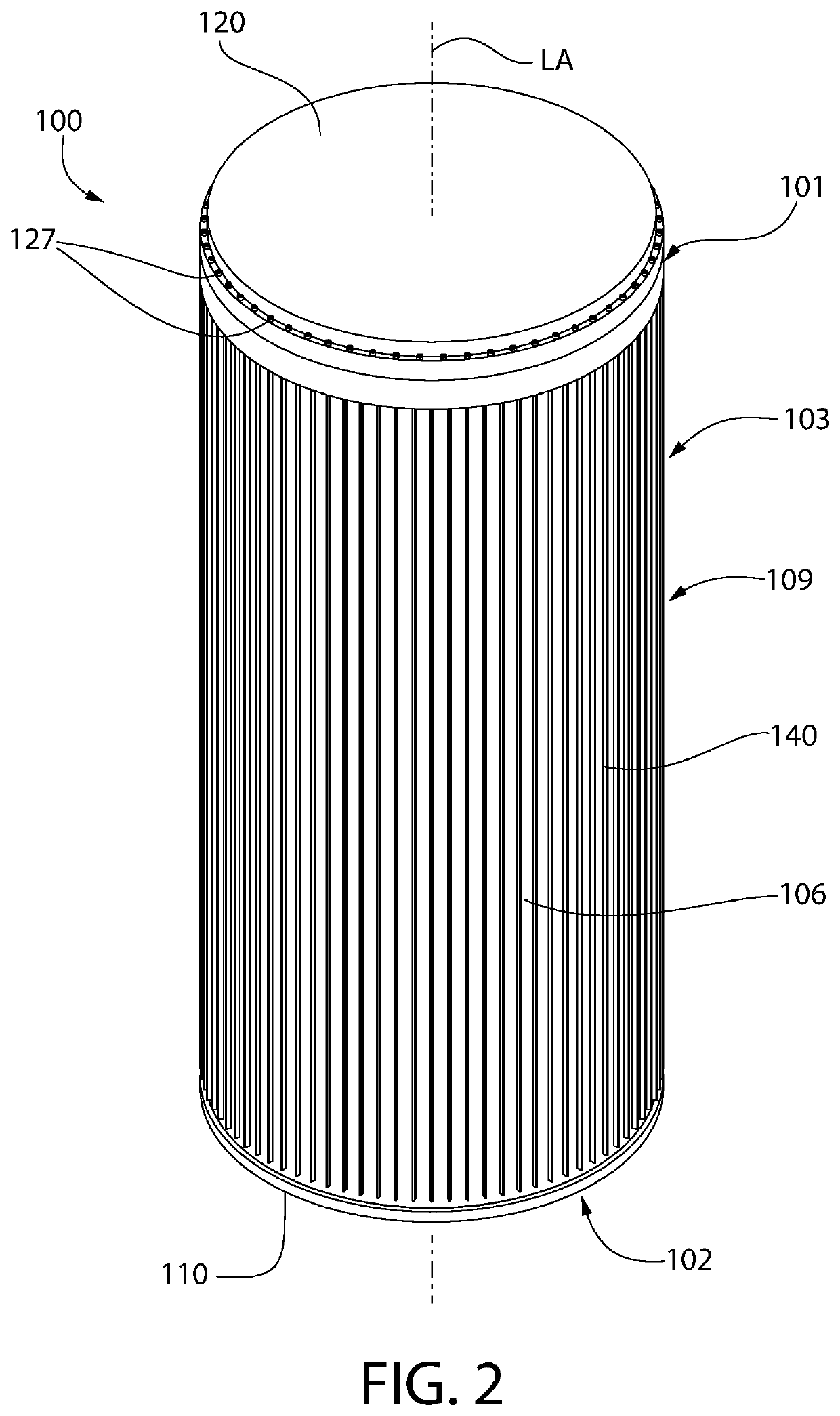
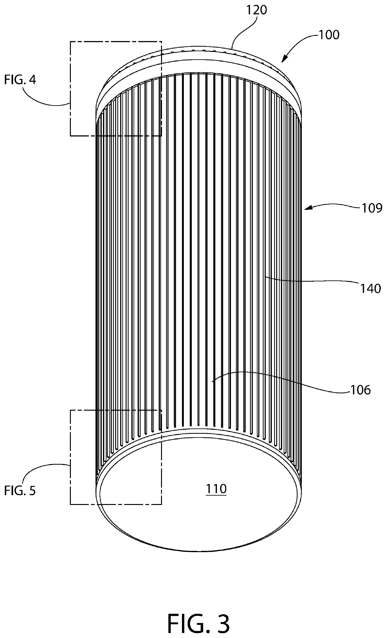
[0052]Canister 100 includes an elongated cylindrical body 103 comprising a single shell 106 including an open top 101, an open bottom 102, and sidewall 109 extending therebetween along a vertical longitudinal axis LA of the canister. Axis LA coincides with the geometric vertical centerline of the canister. Canister 100 further includes a bottom baseplate 110 and a top closure lid 120. Shell 106 may be of monolithic unitary structure in one embodiment formed of a single material.

[0053]Shell 106 further includes an inner surface 107 and op...

second embodiment

[0076]FIGS. 15-25 depict a spent nuclear fuel (SNF) canister 200 with compact bolted lid according to the present disclosure in further detail. SNF canister 200 is similar to canister 100. Similar parts will not be described in detail or numbered in the figures for the sake of brevity. There are some notable differences in design. For example, the shell 206 of canister 200 is substantially similar to shell 106 of canister 100 with exception that is does not have a step-shaped outer surface with annular recess. Instead, the inner surface of the shell is step shaped as further described below. In addition, canister 200 may be finless as shown, or alternatively may be equipped with external cooling fins if heat emitted by the SNF is considerable. Top closure lid 220 has a different configuration than lid 120 of canister 100; however, it retains the small profile bolted joint to the canister shell as further described below. In addition, lid 220 of canister 200 has a different sealing a...


PUM


Abstract

A canister for storing spent nuclear fuel includes an elongated shell, baseplate enclosing the bottom end of the shell, and removable top lid bolted to the shell. The shell may have a dual thickness comprising a lower portion with first thickness and upper portion with greater second thickness by comparison. The upper portion is formed by an annular boss defining a fastening portion of the shell including plural threaded bores for engaging the lid bolting. The fastening portion may protrude radially outwards or inwards in different embodiments. The lid has a mounting flange receiving the bolts and is seated on the top end of shell. The mounting flange does not protrude radially beyond the outer surface of the fastener portion to minimize the diameter of the canister for placement inside an outer radiation shielded overpack or cask for transport / storage. The shell may optionally include cooling fins.

Description

CROSS-REFERENCE TO RELATED APPLICATIONS[0001]This application claims the benefit of U.S. Provisional Application No. 62 / 772,986 filed Nov. 29, 2018, which is incorporated herein by reference in its entirety.BACKGROUND[0002]The present invention relates generally to systems for storing used or spent nuclear fuel, and more particularly to an improved nuclear fuel cask which forms part of the storage system.[0003]In the operation of nuclear reactors, the nuclear energy source is in the form of hollow zircaloy tubes filled with enriched uranium, collectively arranged in multiple assemblages referred to as fuel assemblies. When the energy in the fuel assembly has been depleted to a certain predetermined level, the used or “spent” nuclear fuel (SNF) assemblies are removed from the nuclear reactor. The standard structure used to package used or spent fuel assemblies discharged from light water reactors for off-site shipment or on-site dry storage is known as the fuel basket. The fuel baske...

Claims


Application Information

Patent Timeline
Patent Type & Authority Patents(United States)
IPC IPC(8): G21F5/008G21F5/10G21F5/12G21F5/012
CPCG21F5/008G21F5/10G21F5/12G21F5/012
Inventor SINGH, KRISHNA P.
Owner HOLTEC INT
Why Eureka
Try Eureka