MnAl alloy and manufacturing method therefor

a technology of mnal alloy and manufacturing method, which is applied in the direction of magnetic materials, inductance/transformer/magnet manufacturing, magnetic bodies, etc., can solve the problems of difficult phase transition to ferromagnetism by magnetic field, difficult to form antiferromagnetic structure, and difficult to apply metamagnetic materials to current limiters. achieve the effect of enhancing saturation magnetization, enhancing saturation magnetization, and enhancing saturation magnetization

Active Publication Date: 2022-04-05
TDK CORPARATION
View PDF9 Cites 0 Cited by
  • Summary
  • Abstract
  • Description
  • Claims
  • Application Information

AI Technical Summary

Benefits of technology

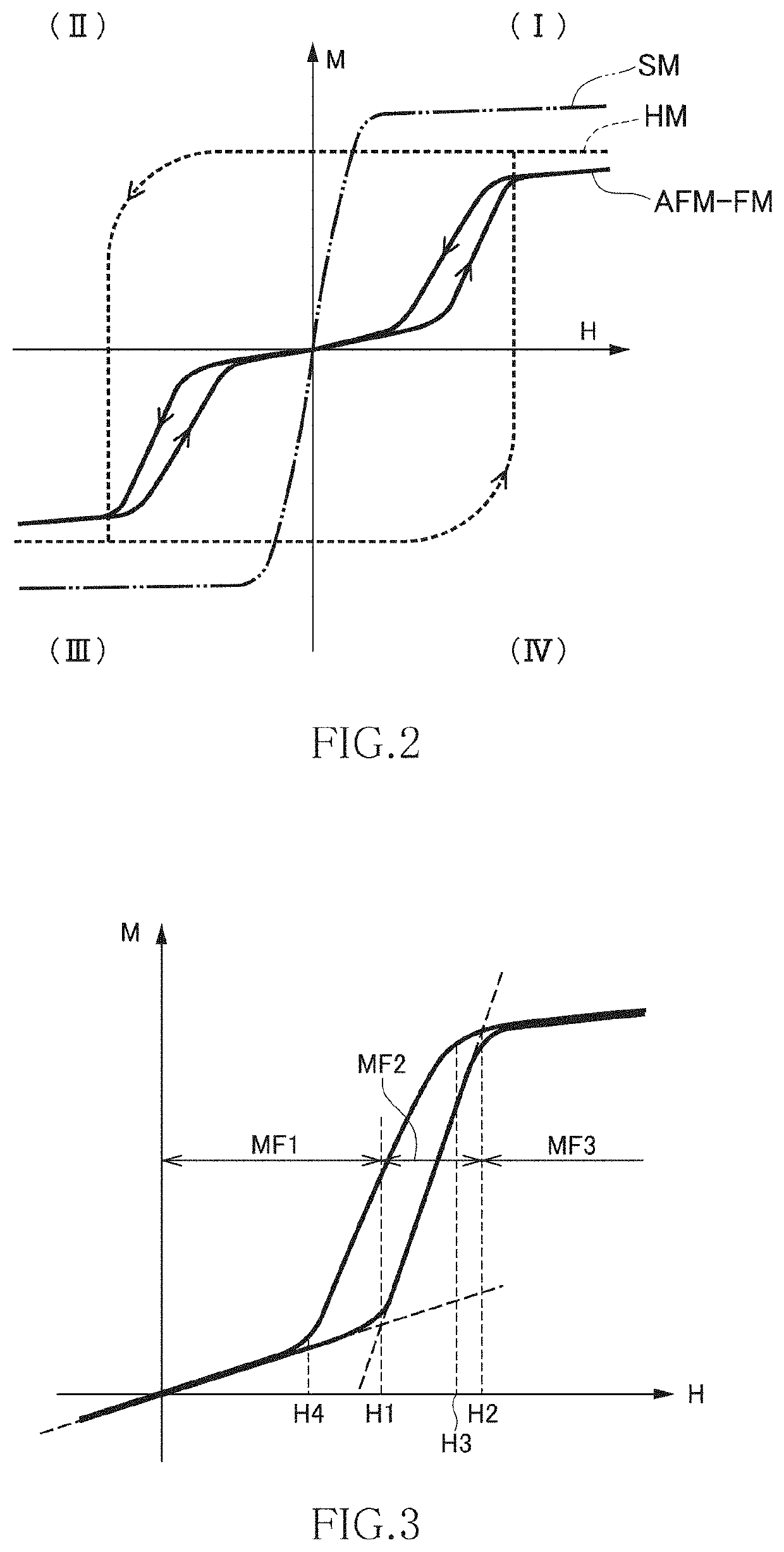
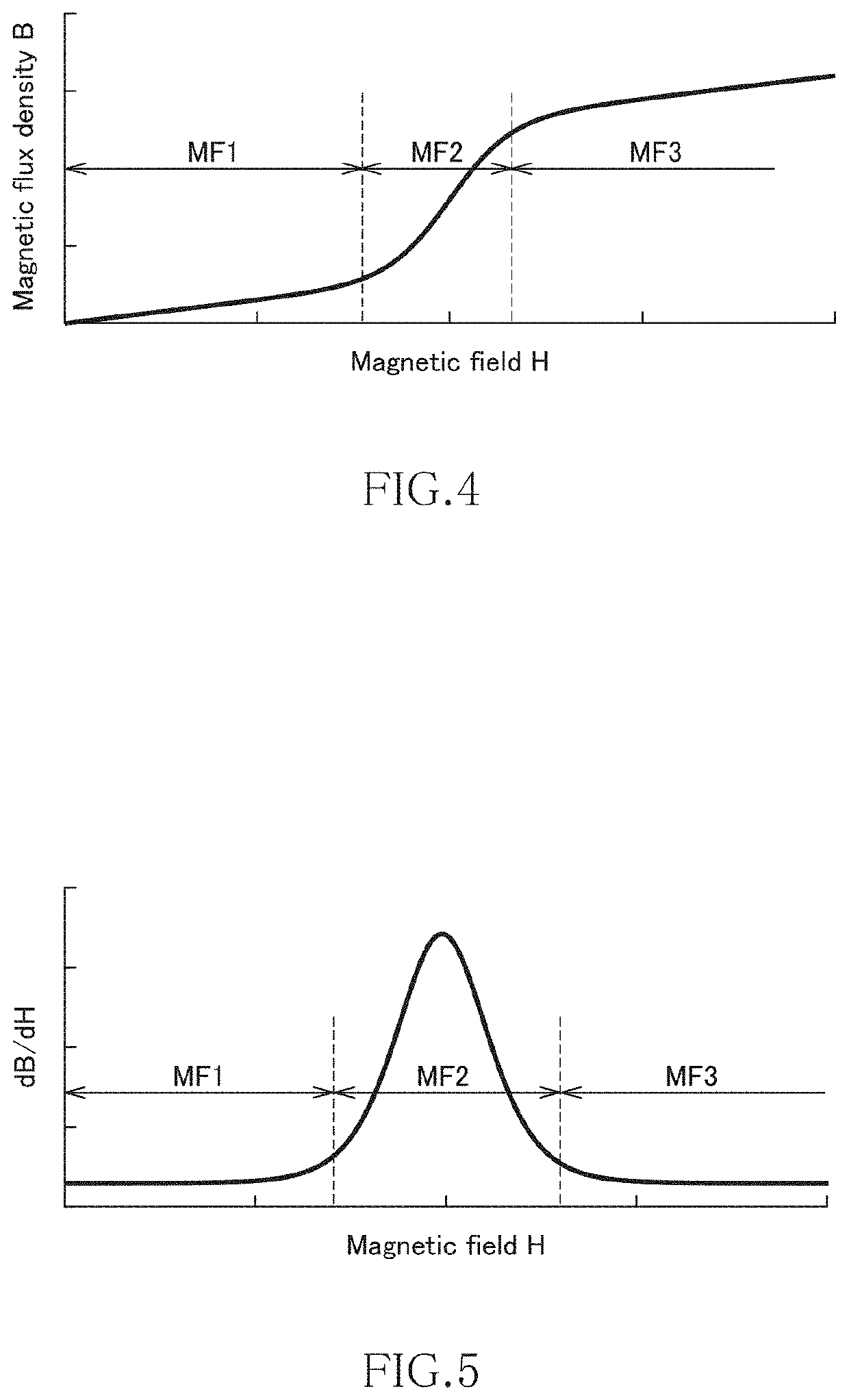
[0006]To solve the above problem and attain the object, the present inventor focused on a meta magnetic material (hereinafter, referred to as “AFM-FM transition type metamagnetic material”) of a type undergoing transition from antiferromagnetism to ferromagnetism by a magnetic field. This is for the following reason: the AFM-FM transition type metamagnetic material exhibits metamagnetism at a temperature equal to or less than the Neel temperature where the antiferromagnetism order disappears, so that, unlike a metamagnetic material (hereinafter, referred to as “PM-FM transition type metamagnetic material”) of a type undergoing transition from paramagnetism to ferromagnetism, it is not necessary to maintain a narrow temperature zone around the Curie temperature.
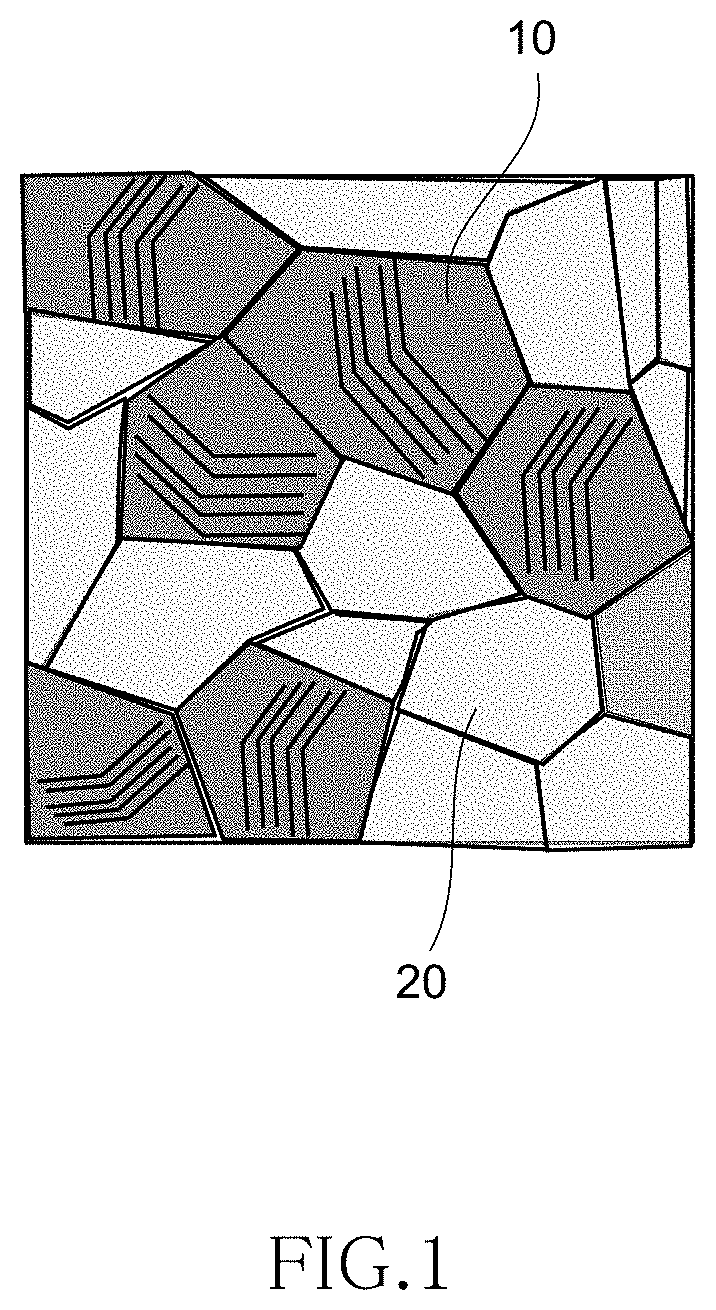
[0009]When the ratio of the τ-MnAl phase is A, by setting the value of A so as to satisfy 75%≤A≤99%, saturation magnetization can be enhanced, and by setting the value of A so as to satisfy 95%≤A≤99%, saturation magnetization can be further enhanced. Further, when the ratios of the γ2-MnAl phase and β-MnAl phase are B and C, respectively, by setting the values of B and C so as to satisfy B<C, saturation magnetization can be enhanced, and by setting the values of B and C so as to satisfy 0.01≤B / C≤0.17, saturation magnetization can be further enhanced.
[0010]The MnAl alloy according to the present invention preferably has the magnetic structure of the τ-MnAl phase preferably has an antiferromagnetic structure. By using the MnAl-based alloy whose antiferromagnetism is stable in a non-magnetic field state before phase transition, an AFM-FM transition type meta magnetic material is realized. When the stability of the antiferromagnetic state is too high, it is impossible to make phase transition to ferromagnetism by a magnetic field. On the other hand, when the stability of the antiferromagnetism is too low, phase transition to ferromagnetism may occur even with non-magnetic field or very weak magnetic field. In the MnAl alloy, an antiferromagnetic state is adequately stable, so that by imparting AFM-FM transition type metamagnetism, it is possible to obtain metamagnetism over a wide temperature range.
[0012]A MnAl alloy manufacturing method according to the present invention includes a step of depositing a MnAl alloy by electrolyzing molten salt containing a Mn compound and an Al compound at a temperature of 350° C. or more and 450° C. or less and a step of applying heat treatment to the MnAl alloy at a temperature of 400° C. or more and less than 600° C. By thus applying heat treatment to the MnAl alloy formed by a molten salt electrolysis method performed at a predetermined temperature, it is possible to impart metamagnetism to the MnAl alloy and to enhance saturation magnetization.

Problems solved by technology

Thus, practically, it is difficult to apply the metamagnetic materials to a current limiter and the like.
When the stability of the antiferromagnetic state is too high, it is impossible to make phase transition to ferromagnetism by a magnetic field.
In addition, when Mn atoms are substituted on the Al site, the super exchange interaction does not occur between Mn atoms on the Mn site, and thus an antiferromagnetic structure is difficult to form.

Method used


Image

  • MnAl alloy and manufacturing method therefor
  • MnAl alloy and manufacturing method therefor
  • MnAl alloy and manufacturing method therefor

Examples


examples

[0075]First, an electrodeposition apparatus having the structure illustrated in FIG. 7 was prepared. As the cathode 5, a Cu plate having a thickness of 3 mm cut out so as to set the immersion area into the molten salt 3 to a size of 5 cm×8 cm was used. As the anode 6, an Al plate having a thickness of 3 mm cut out so as to set the immersion area into the molten salt 3 to a size of 5 cm×8 cm was used.

[0076]Then, 50 mol % anhydrous AlCl3 which is an Al compound, 50 mol % NaCl which is another halide, and 1 mass % MnCl2 dehydrated in advance as the Mn compound are weighed and thrown into the alumina crucible 2 such that the total weight thereof was 1200 g. Thus, the weight of MnCl2 was g. The dehydration was performed by heating MnCl2 hydrate at about 400° C. for four hours or longer in an inert gas atmosphere such as N2.

[0077]The alumina crucible 2 into which the materials had been thrown was moved inside the sealed vessel 1, and the materials were heated to 350° C. by the electric fu...


PUM

PropertyMeasurementUnit
temperatureaaaaaaaaaa

Abstract

A MnAl alloy according to the present invention exhibits metamagnetism and has crystal grains containing a τ-MnAl phase and crystal grains containing a γ2-MnAl phase and a β-MnAl phase. When the ratio of the τ-MnAl phase is A, 75%≤A≤99% is preferably satisfied, and when the ratios of the γ2-MnAl phase and β-MnAl phase are B and C, respectively, B<C is preferably satisfied. Thus, it is possible to obtain metamagnetism over a wide temperature range, particularly, over a temperature range of −100° C. to 200° C. and to enhance saturation magnetization.

Description

BACKGROUND OF THE INVENTIONField of the Invention[0001]The present invention relates to a MnAl alloy and a manufacturing method therefore and, more particularly, to a MnAl alloy having metamagnetism and a manufacturing method therefor.Description of Related Art[0002]A MnAl alloy is hitherto known as a magnetic material. For example, the MnAl alloy disclosed in JP S36-11110 B has a tetragonal structure and has a Mn / Al ratio of 5:4 to thereby exhibit magnetism. Further, J P 2017-45824 A describes that by making a first phase composed of MnAl alloy having a tetragonal structure and a second phase composed of Al8Mn5 crystal grains coexist, the MnAl alloy can be utilized as a permanent magnet having high coercive force.[0003]Further, as disclosed in JP 2014-228166 A, it is known that some of the magnetic materials having Mn as a main constituent element exhibit metamagnetism. The metamagnetism refers to a property in which magnetism undergoes transition from paramagnetism or antiferromag...

Claims


Application Information

Patent Timeline
Patent Type & Authority Patents(United States)
IPC IPC(8): C22F1/18C25D3/66C22C22/00
CPCC22F1/18C22C22/00C25D3/66H01F1/015H01F41/02C25C3/36
Inventor SATOH, SUGURU
Owner TDK CORPARATION
Why Eureka
Try Eureka