Multi-zone heat sink for printed circuit boards

Active Publication Date: 2022-04-19
DSPACE DIGITAL SIGNAL PROCESSING & CONTROL ENG
View PDF15 Cites 0 Cited by
  • Summary
  • Abstract
  • Description
  • Claims
  • Application Information

AI Technical Summary

Benefits of technology

[0005]It is therefore an object of the present invention to reduce the spa

Problems solved by technology

The mounting of a heat sink can even be counterproductive, therefore, because the heat sink transports waste heat from high-performance components to components with low temperature tolerance, thus

Method used


Image

  • Multi-zone heat sink for printed circuit boards
  • Multi-zone heat sink for printed circuit boards

Examples


Example

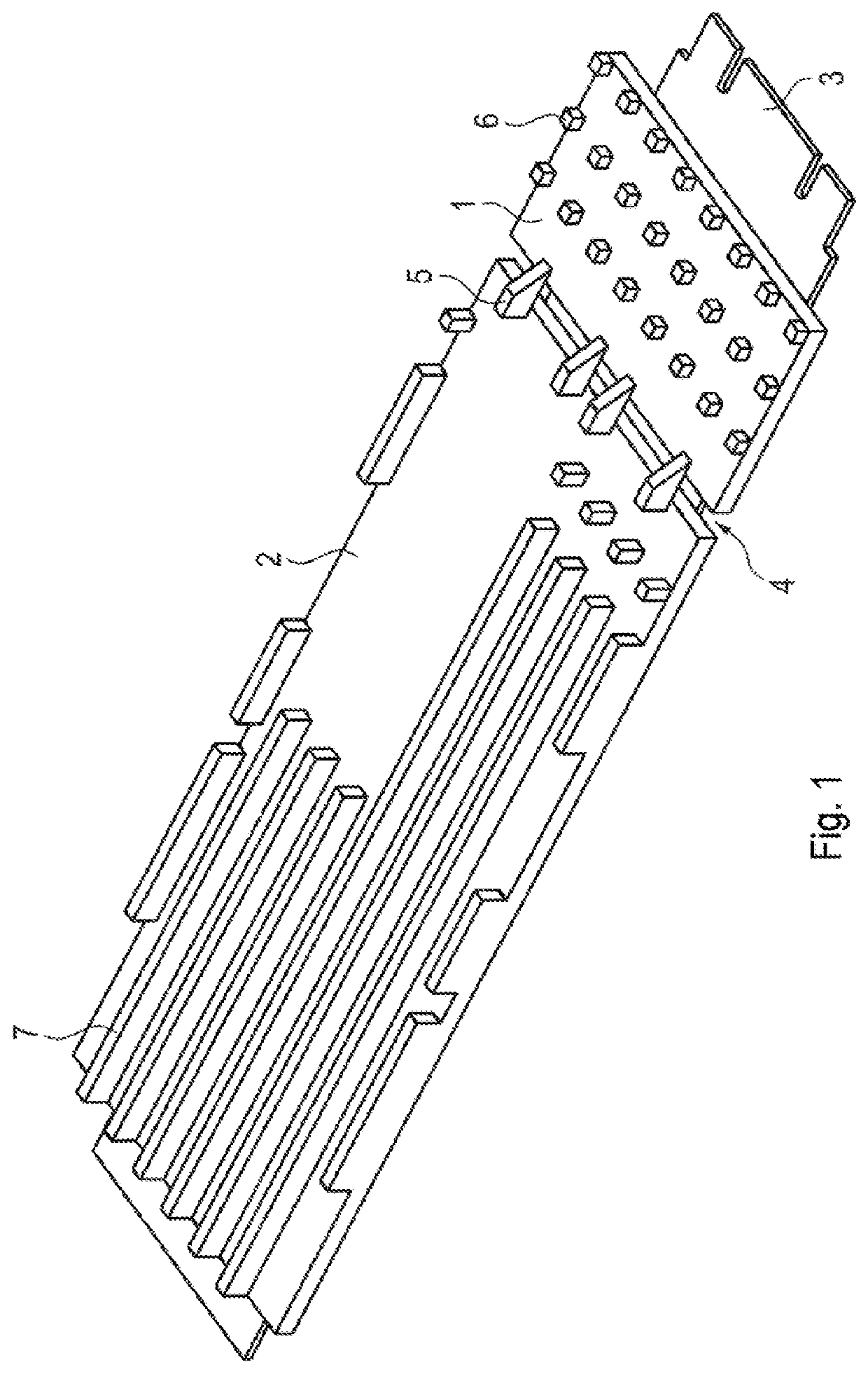
[0018]In FIG. 1, a heat sink resting on a large area of a printed circuit board 3 is depicted with a first sub-area 1 and a second sub-area 2. A gap 4 that crosses the full width of the printed circuit board extends between the first sub-area 1 and the second sub-area 2; this gap forms an air gap between the first sub-area 1 and the second sub-area 2, and consequently isolates the first sub-area 1 thermally from the second sub-area 2. Four metallic bridges 5 span the gap 4 and form a mechanical connection of the first sub-area 1 to the second sub-area 2.

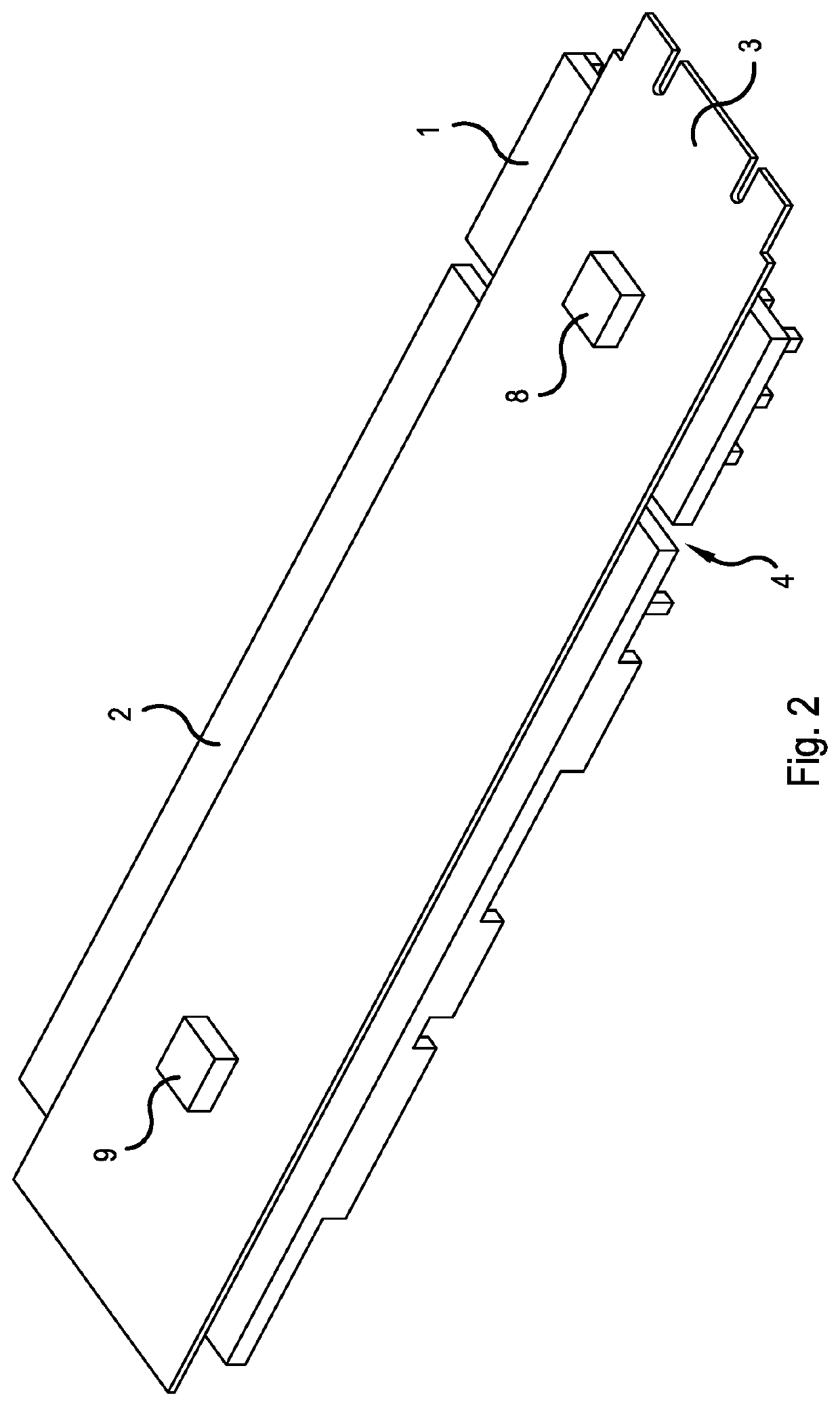
[0019]Arranged on the printed circuit board 3 are electronic components, not visible beneath the heat sink in FIG. 1. As shown in FIG. 2, a first electronic component 8, for example a flash controller, is arranged underneath the first sub-area 1, and a second electronic component 9, for example a flash memory chip, underneath the second sub-area 2. The flash controller can be properly operated up to an operating temperature of 125° C...


PUM


Abstract

A heat sink with a first sub-area and a second sub-area, designed for contacting a large area of a printed circuit board populated with electronic components. A thermal isolation extends between the first sub-area and the second sub-area, and a rigid mechanical connection that spans the thermal isolation connects the first sub-area to the second sub-area. As a result, the heat sink allows an assignment of sub-areas to electronic components on the printed circuit board, and contributes to mechanical stabilization of the printed circuit board.

Description

[0001]This nonprovisional application claims priority under 35 U.S.C. § 119(a) to German Patent Application No. 10 2019 135 060.3, which was filed in Germany on Dec. 19, 2019, and which is herein incorporated by reference.BACKGROUND OF THE INVENTIONField of the Invention[0002]The present invention relates to thermal management of computer systems.Description of the Background Art[0003]Numerous computer systems developed for outdoor use in vehicles are found on the market, for example the DRIVE AGX platform from NVIDIA, the “Rugged Embedded Computer” line by Crystal Group, and the Autera AutoBox from dSPACE. Typical requirements for such computer systems are compactness in order to be able to use them in cramped conditions, as well robustness and vibration resistance. Particularly because of current efforts to develop highly automated vehicles, there is a demand for such development systems designed for outdoor use that are additionally equipped with high computing capacity and there...

Claims


Application Information

Patent Timeline
IPC IPC(8): H05K1/02H05K7/20H05K1/18
CPCH05K1/0203H05K1/181H05K7/2039H05K7/20518H05K2201/066G06F1/206H05K7/205H01L23/3672
Inventor BREICHER, ROBERTNGUYEN, VAN SONHENKEL, JOHANNES
Owner DSPACE DIGITAL SIGNAL PROCESSING & CONTROL ENG
Why Eureka
Try Eureka