
Control system for a battery system

a control system and battery technology, applied in the field of control system for battery system, can solve the problems of gate driver stage level, and related art system does not consider the functional safety and availability of dc-dc converters, etc., to achieve the effect of satisfactory asil b requirements and contributing to the functional availability of the battery system

Active Publication Date: 2022-05-10
SAMSUNG SDI CO LTD
View PDF14 Cites 0 Cited by
  • Summary
  • Abstract
  • Description
  • Claims
  • Application Information

AI Technical Summary

Benefits of technology

[0011]According to embodiments of the present invention, a control system for a battery system, such as an improved DC-DC converter for a battery system, which contributes to the functional availability of the battery system and satisfies ASIL B requirements, is provided.
[0028]In one embodiment, at least one of the first and second microcontrollers is configured to perform at least one control function with respect to the battery system. The at least one control function may include measurements of cell voltages, cell currents, cell resistances, and / or cell capacities. The control functions may also include active or passive balancing of cell voltages or cell currents of a plurality of battery cells. Accordingly, the control system may be configured to detect a voltage of at least one battery cell and / or may be configured to balance the voltages of a plurality of battery cells. Further, the first and / or second microcontrollers may be configured as one of a battery management system (BMS), battery system manager (BSM), or cell supervision circuit (CSC). However, only one of the first and second microcontrollers may be configured to perform one or more of these control functions to simplify the setup and reduce the component costs for the control system and the battery system.
[0029]According to another embodiment, the first microcontroller is connected to the first fraction via a first gate driver stage, and the second microcontroller is connected to the second fraction via a second gate driver stage. For example, each of the microcontrollers is connected to its respective single phase DC-DC converters via its own gate driver stage. But an error (e.g., a fault) may occur at the gate driver stage level. Hence, using only a single gate driver stage for all of (or both of) the microcontrollers could reduce the desired redundancy of DC-DC conversion operations. Therefore, by respectively providing individual gate driver stages for the individual microcontrollers, redundancy is improved. And by detecting a fault state on the control level and / or on the output level of the control system as described above, and because an error of the gate driver stage level may be reliably detected, for example, on the output level, reliability is further improved.
[0034]Thus, a voltage is provided to the second output node in a reliable manner. For example, an output voltage is provided to the second output node even if a malfunction occurs in part of (e.g., some of) the N single phase DC-DC converters, thereby providing improved redundancy. Improved redundancy on the control level is provided by the first microcontroller and the second microcontroller communicating with each other via the data line. Further, improved redundancy is provided on level of the single phase DC-DC converters by providing the first fraction N1 of single phase DC-DC converters and the second fraction N2 of single phase DC-DC converters (e.g., by splitting the N single phase DC-DC converters into the first and second fractions).
[0036]Another embodiment of the battery system further includes a switching unit that is interconnected between the battery cell stack and the first output node as well as the N-phase DC-DC converter. The switching unit may include a first unit switch that is interconnected between the battery cell stack and the first output node, and the first unit switch may set a path between the battery cell stack and the first output node to be either conductive or non-conductive. The switching unit may further include a second unit switch that is interconnected between the battery cell stack and the N-phase DC-DC converter, such as an input node of the N-phase DC-DC converter, and the second unit switch may set a path between the battery cell stack and the N-phase DC-DC converter to be either conductive or non-conductive. The switching unit may further include a third unit switch that is interconnected between the first output node and the N-phase DC-DC converter, such as an input node of the N-phase DC-DC converter, and the third unit switch may set a path between the first output node and N-phase DC-DC converter to be either conductive or non-conductive. The switching unit increases the operative safety of the battery system as it allows for the disconnection of the battery cell stack from any loads connected thereto, either connected via the first output node or the DC-DC converter and the second output node. The switching unit also increases the liberty of the user in using the DC-DC converter as a push pull converter in different ways.

Problems solved by technology

Static control of battery power output and charging may not be sufficient to meet the dynamic power demands of various electrical consumers connected to the battery system.
However, the related art systems do not consider the functional safety and availability of the DC-DC converters.
But an error (e.g., a fault) may occur at the gate driver stage level.
Hence, using only a single gate driver stage for all of (or both of) the microcontrollers could reduce the desired redundancy of DC-DC conversion operations.

Method used


Image

  • Control system for a battery system
  • Control system for a battery system
  • Control system for a battery system

Examples


first embodiment

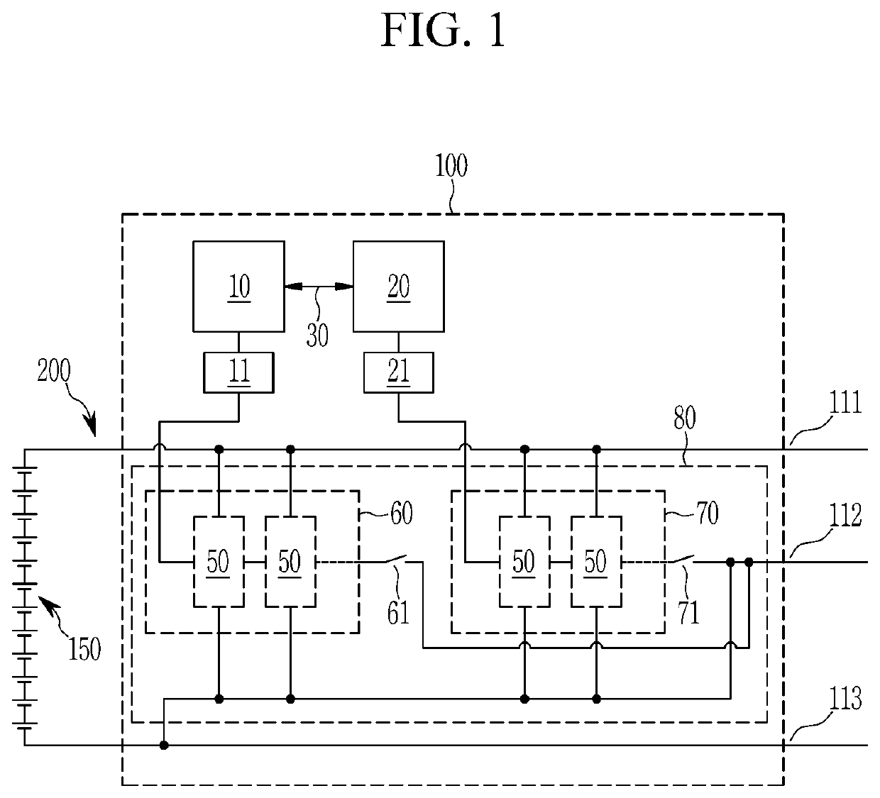
[0053]FIG. 1 is a schematic drawing of a battery system 200, for example, of an electric vehicle, with a control system 100 according to the present invention. The battery system 200 includes a battery cell stack 150 including a plurality of battery cells interconnected in series and / or in parallel between a first stack node and a second stack node. The first stack node is connected to a first output node 111 of the battery system 200, and the second stack node is connected to a ground node 113 of the battery system 200.

[0054]An N-phase DC-DC converter 80 is interconnected between the battery cell stack 150 and the nodes 111, 113 and includes a plurality of (e.g., N, wherein N is a whole number greater than one) single phase DC-DC converters 50. Each of the single phase DC-DC converters 50 has a first input node connected to the first stack node and a second input node connected to the second stack node. Each of the single phase DC-DC converters 50 also has an output node that is co...

second embodiment

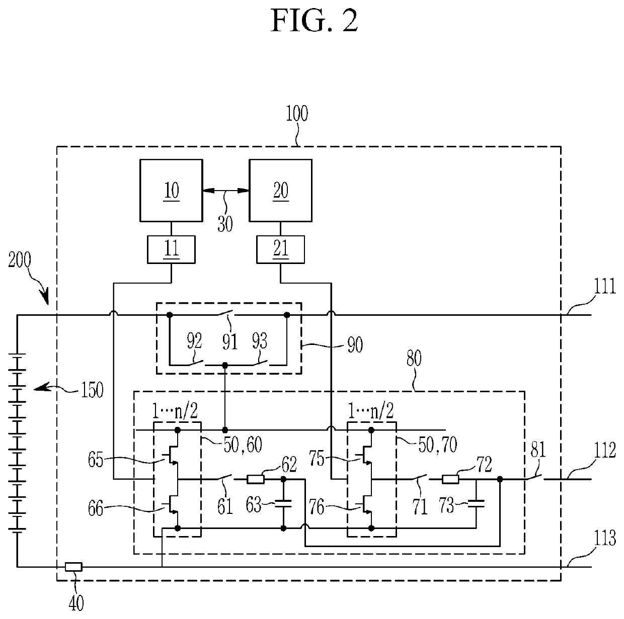
[0058]FIG. 2 is a schematic drawing of a battery system 200 with a control system 100 according to a Insofar the battery system 200 is similar to the battery system 200 shown in FIG. 1, the same elements are denoted by same reference numbers and a repeated description thereof may be omitted.

[0059]In the control system 100 shown in FIG. 2, only one single phase DC-DC converter is shown for each of the first fraction 60 and second fraction 70 from among the DC-DC converters for ease of illustration. Each of the single phase DC-DC converters 50 includes a pair of MOSFET switches 65, 66 / 75, 76 and is thus provided as a push-pull-converter. The first fraction 60 of DC-DC converters 50 is connected to the second output node 112 of the control system 100 via a shared first output switch 61, first output inductance (e.g., a first output inductor) 62, and first output capacitance (e.g., a first output capacitor) 63. The second fraction 70 of DC-DC converters 50 is connected to the second ou...

third embodiment

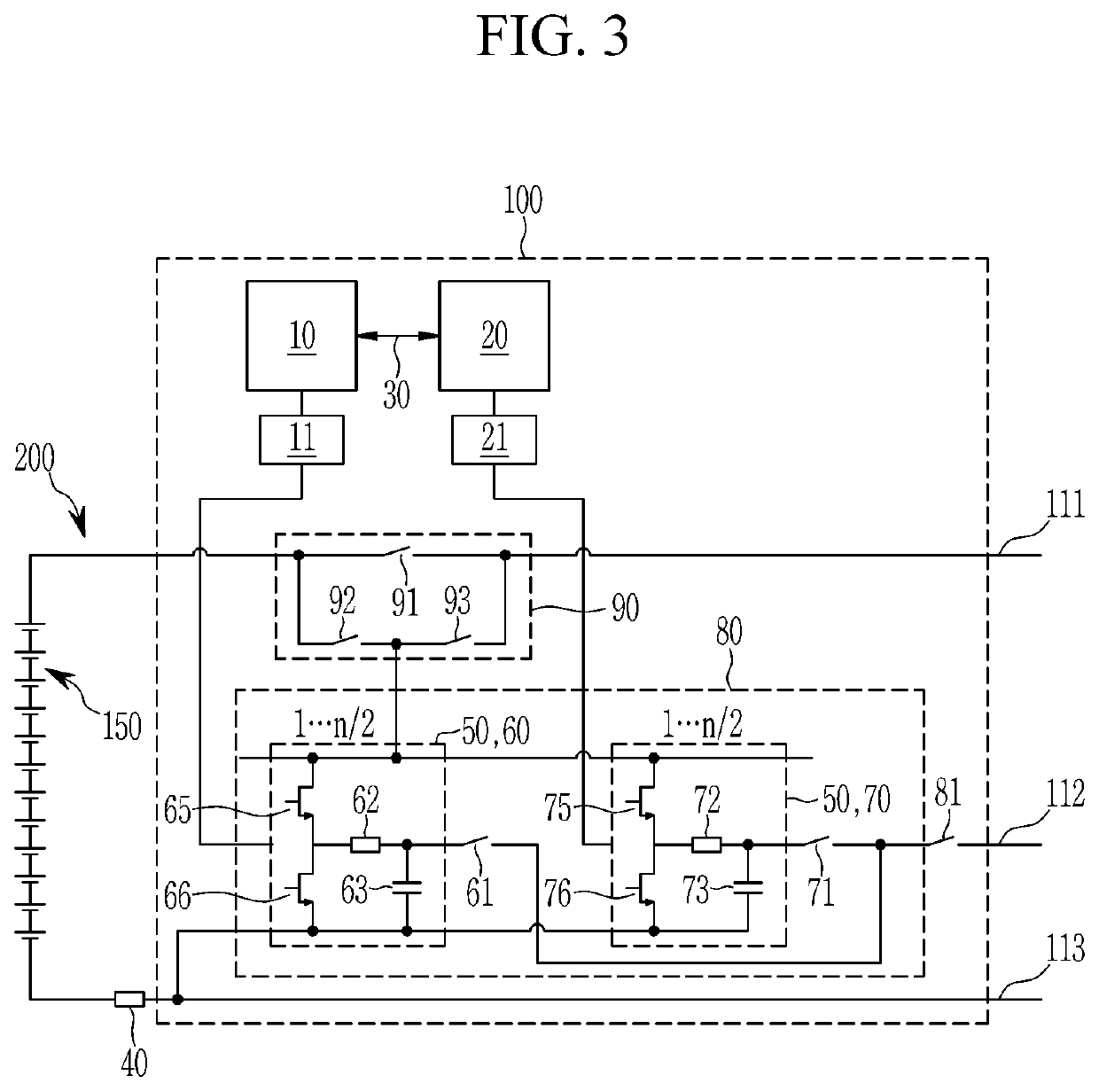
[0060]FIG. 3 is a schematic drawing of a battery system 200 with a control system 100 according to a Insofar as the battery system 200 shown in FIG. 3 is similar to the battery systems 200 shown in FIGS. 1 and 2, the same elements are denoted by same reference numbers and a repeated description thereof may be omitted.

[0061]In the control system 100 shown in FIG. 3, each of the single phase DC-DC converters 50 of the first fraction 60 includes an inductance (e.g., an inductor) 62 and a capacitor (e.g., a capacitance) 63, and each of the single phase DC-DC converters 50 of the second fraction 70 includes an inductance 72 and a capacitor 73. Each of these single phase DC-DC converters 50 further includes the pair of MOSFET switches 65, 66 / 75, 76 and is thus provided as a buck-type push-pull-converter.

[0062]FIGS. 4A-C illustrate a switching unit (e.g., a switch) 90 of the battery system 200 according to the second and / or the third embodiment as illustrated in FIGS. 2 and 3, respectivel...


PUM


Abstract

A control system for a battery system is provided. The control system includes: an N-phase DC-DC converter including N single phase DC-DC converters (wherein N is a whole number greater than one); a first microcontroller configured to control a first fraction of the N single phase DC-DC converters; and a second microcontroller configured to control a second fraction of the N single phase DC-DC converters. The first and second microcontrollers are connected to each other via a data line. In a first operation mode, control operations of the first microcontroller and the second microcontroller are synchronized via the data line to commonly control the N single phase DC-DC converters, and in a second operation mode, the first microcontroller and the second microcontroller independently control the first fraction and the second fraction, respectively.

Description

CROSS-REFERENCE TO RELATED APPLICATION[0001]This application claims priority to and the benefit of European Patent Application No. 19180263.6, filed in the European Patent Office on Jun. 14, 2019, and Korean Patent Application No. 10-2020-0040458, filed in the Korean Intellectual Property Office, on Apr. 2, 2020, the entire contents of which are incorporated herein by reference.BACKGROUND1. Field[0002]Aspects of embodiments of the present invention relate to a control system for a battery system and to a battery system including such a control system.2. Related Art[0003]A rechargeable (or secondary) battery differs from a primary battery in that it is designed to be repeatedly charged and discharged, while the latter is designed to provide an irreversible conversion of chemical to electrical energy. Low-capacity rechargeable batteries are used as power supplies for small electronic devices, such as cellular phones, notebook computers, and camcorders, while high-capacity rechargeable...

Claims


Application Information

Patent Timeline
Patent Type & Authority Patents(United States)
IPC IPC(8): H02M3/158G01R31/40G01R31/00H02J1/10H02J7/00
CPCH02M3/1584G01R31/006G01R31/40H02J1/102H02J7/0013H02M3/1586H02M1/325Y02T10/70
Inventor RENATO, MANDICHOFER, MAXIMILIAN
Owner SAMSUNG SDI CO LTD
Learn More