
Refrigerator fan device and ultra-low temperature freezer

a fan device and ultra-low temperature technology, applied in the direction of cooling fluid circulation, domestic cooling devices, lighting and heating devices, etc., can solve the problems of fan tip noise, disturbing noise, and often perceived disturbing noise of fan devices of this kind

Active Publication Date: 2022-05-31
EPPENDORF SE
View PDF22 Cites 0 Cited by
  • Summary
  • Abstract
  • Description
  • Claims
  • Application Information

AI Technical Summary

Benefits of technology

[0006]Therefore, the object of the present invention is to improve a refrigerator fan device according to the preamble of the main claim, in particular intended for so-called ultra-low temperature refrigerators, in terms of their noise behavior and in particular to also provide an improved fan device that improves energy efficiency of both the fan motor and the cooling units (heat exchanger, compressor) subject to its air cooling. A constructively simple realization that minimizes the amount of hardware needed is an aspect to be observed in particular, and it should preferably also be ensured that an improved fan device of this kind can be operated easily and reliably in different operating environments, in particular operating environments with different country-specific nominal mains voltages.
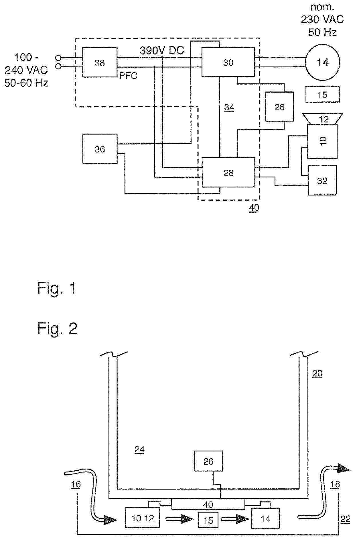
[0008]In an advantageous manner according to the invention, first of all, the fan motor is realized as a brushless speed-controlled DC motor. In a particularly advantageous manner according to the invention, this allows the fan motor speed not only to be controlled, according to the invention, as a function of an operating and / or used cooling space temperature but also to be realized in such a manner that the fan motor can be operated in a particularly simple manner by means of motor electronics or ballast electronics that are typically used already to operate the ULT refrigerator itself and which, being typically provided with voltage converter means for processing different input supply network AC voltages in an additionally advantageous manner, can then provide a constant DC voltage at the output of advantageous voltage converter means of this kind, from which an operating voltage for the DC motor according to the invention can be generated or derived and, if required, controlled.
[0013]In connection with integrated motor electronics or ballast electronics for both the (at least one) refrigerator compressor (but preferably multiple refrigerator processors provided as a cascade) and the fan motor, it is additionally advantageous for said electronics to be provided with a power factor correction (PFC) so as to provide universality for various (national) mains voltage environments as well as minimize potential circuit feedback into such a (public) power supply network.
[0014]An especially elegant embodiment which is useful for sensitive operating environments consists in the delay means which are provided according to an embodiment and which, again being preferably realized in connection with the integrated electronics, act on the refrigerator compressor and are configured such that in response to an activation or operation start signal activating the refrigerator, the fan motor is activated prior to activation of the refrigerator compressor, more specifically a predetermined time interval prior to activation of the refrigerator compressor as per an embodiment according to the invention. For example, a preferred embodiment of this kind can, with significant effect on operational reliability of a refrigerator device realized in this way, help prevent a problem that the cooling circuit operated by the refrigerator compressor and, at the ultra-low temperatures preferred at hand, often containing flammable refrigerants, has a leak which can pose a danger of explosion in the case of possible sparking caused by the activation of the compressor. In this regard, the solution according to an embodiment of the invention of activating the fan motor a predetermined time prior to switching on the refrigerator compressor has the effect that the cooling air flow removes any leaked refrigerant or at least dilutes it far enough that the remaining mixture is no longer flammable in the case of the leak and the danger of explosion is thus significantly reduced. A typical time interval to be further preferably set for such a delay of the compressor activation relative to activation of the fan motor is ca. 5 s, time intervals configured according to the invention offering reference points for how this delay should be determined depending on the configuration of a correspondingly equipped refrigerator and on operating environments and conditions.
[0015]In particular the use as per the invention of a brushless DC motor for realizing the fan motor often offers the option that a speed-proportional signal is available for evaluating or monitoring the operating mode of the fan motor (whether via the control loop driving the DC motor or via a separate return channel of motor control electronics). By evaluating such a (current) speed signal of the fan motor according to the invention, possible malfunctions can be detected and the cooling or compressor operation of a correspondingly equipped refrigerator device can be influenced in response, for example. For instance, in response to activation of a fan motor according to the invention, monitoring of the associated speed signal helps determine whether said motor works at an intended speed (such as by comparing it to electronically stored target values, for example), and if the speed falls short of a speed threshold, a malfunction can be assumed (such as a fan motor defect or a blockage in the air duct), whereupon an error report can be output or starting of the refrigerator compressor may even be disabled. Additionally or alternatively, with a fan motor speed detection or monitoring of this kind, the fan motor speed can be put in relation to the operating and / or used cooling space temperature detected according to the invention, and when a predetermined deviation from intended target values or target value ranges occurs, corresponding error signals can be output or compressor operation can be deactivated so as to avoid potential damage to the refrigerator.

Problems solved by technology

Aside from electrical energy consumption and the compressors as well as the fan motors used for cooling and to remove heat from the heat exchanger, noise emitted by these fan motors especially during continuous operation plays an increasingly important role.
Depending on a position of a refrigerator system typically provided with the generic fan device, fan noise of a fan device of this kind is often perceived as disturbing, especially when the refrigerator compressor (commonly also a plurality of compressors disposed in the form of a so-called cascade) is running at reduced cooling output or reduced compressor motor speed (a compressor of this kind often being additionally sound-insulated) in a stationary (continuous) cooling mode at or close to a target temperature.
In this case, not only the fan motor itself (which is typically operated at a fixed speed and designed as an AC motor) causes potentially disturbing noise, but also the blades of the fan rotor, which generate air flow and are typically operated at speeds of about 1300 to 1400 min−1, cause disturbing noise (so-called fan tip noise, i.e. swooshing caused by fan blades).
Since generic fan motors themselves are usually operated without speed control or RPM control (not least because the generically used motors do not easily allow for speed control for cost reasons, for example) and operation of a fan motor typically involves controlling an assigned compressor (i.e. the fan motor is operated constantly synchronous with the refrigerator compressor), fan motor operation and the accompanying noise emission are continuous during compressor operation at a basically unchanged high noise level.
However, this leads to a disadvantage in efficiency in operating situations of reduced cooling output of the refrigerator compressor (i.e. during stationary operation of a target cooling temperature, for example).
This is because, even in this case, the cooling circuit will be subjected to the full fan output of the heat exchanger and of the fan device, which, in turn, causes increased compressor output in a way that reduces energy efficiency because (during a cooling output operation reduced in this way) the refrigerator compressor will not (no longer) run at an optimized working temperature or on an optimized working point because of the high air flow still continuing to flow.

Method used


Image

  • Refrigerator fan device and ultra-low temperature freezer

Examples


Embodiment Construction

[0021]As the schematic block diagram of FIG. 1 illustrates logically and functionally and as the geometrical illustration of FIG. 2 shows, a fan motor 10 realized as a brushless DC motor and having a fitted fan rotor 12 is placed relative to a heat exchanger (condenser) 15, which dimensioned for ultra-low temperature cooling purposes and includes a refrigerator compressor 14 of a cooling circuit (not shown), in such a manner that a cooling air flow generated by the fan rotor 12, coming from an inlet 16 (suitably covered by a fan grill, a filter or the like in a manner not shown) and conducted toward an outlet 18 can be applied from an ambient air environment of the refrigerator 20 schematically shown in FIG. 2. More precisely, said outlined air-conduction path 16-10-12-15-14-18 is formed in a bottom area 22 of a refrigerator housing of the refrigerator 20, which offers an interior 24 as a used cooling space for receiving cooled goods which, in the embodiment described, can be mainta...


PUM


Abstract

A refrigerator fan device, comprising: a fan motor (10) which has a fan rotor (12) and which can be provided in an air duct between an air inlet (16), a refrigerator heat exchanger (15), and / or a refrigerator compressor (14) and an air outlet (18) on or in a refrigerator housing (20, 22), said fan motor (10) being connectable to a unit of the refrigerator, via electrical supply and / or control lines, wherein the fan motor (10) is realized as a brushless speed-controllable DC motor whose operating speed is or can be controlled as a function of an operating and / or used cooling space temperature signal of, the assigned or assignable refrigerator compressor.

Description

BACKGROUND OF THE INVENTION[0001]The present invention relates to a refrigerator fan device. Furthermore, the present invention relates to an ultra-low temperature refrigerator having such a fan device.[0002]It is generally known from the state of the art for refrigerators, in particular ultra-low temperature (ULT) refrigerators, i.e. refrigerators for a used cooling space at a cooling temperature below −40° C., typically even below −60° C. to as far as −80° C. and below, to be provided with fan devices for heat removal of the process heat produced at the heat exchanger (condenser) in the thermodynamic process and, if required, for cooling the refrigerator compressors employed. These fan devices, which typically have at least one fan motor driving a fan rotor, are suitably provided in an air duct, typically on or in the area of a bottom of a refrigerator housing, and guide air entering through an air inlet across the condenser and the compressors and to an air outlet, thus ensuring ...

Claims


Application Information

Patent Timeline
Patent Type & Authority Patents(United States)
IPC IPC(8): F25D11/02F25D17/06H02P29/60F25D17/08
CPCF25D17/067F25D11/02F25D17/08H02P29/60F25B2600/112F25D2317/0666F25D2600/02F25D2600/06F25D2700/122F25D17/06
Inventor CLARKE, SIMONMASON, GEORGEUHLENDORF, RÜDIGER
Owner EPPENDORF SE
Learn More