Insulated submarine cable

a technology of insulated cables and submarines, applied in the direction of insulated cables, insulated conductors, plastic/resin/waxes insulators, etc., can solve the problems of material breakage, failure of insulating properties, and limited use period of such insulated cables

Active Publication Date: 2022-06-07
JDR CABLE SYST
View PDF18 Cites 1 Cited by
  • Summary
  • Abstract
  • Description
  • Claims
  • Application Information

AI Technical Summary

Benefits of technology

[0022]Advantageously, the different lengths of the cable are manufactured to different standards according to the conditions in which those lengths of the cable will be used. For instance, the first length may hang from an offshore platform and descend to the seabed, and the second length may lie along the seabed. The first length may therefore be manufactured to a standard required for a cable which is in air, under axial tension and exposed to sunlight, and the second length may therefore be manufactured to a standard required for a cable which is submerged in water, under compressive pressure and exposed to little or no sunlight. This may help ensure that no length of the cable is over- or under-insulated, that each length has an appropriate core cross-sectional area or thickness, and / or that the dielectric strength of the cable at different cross sections along the length of the cable is appropriate for the conditions that cross section will experience.
[0026]In some embodiments, the insulated submarine cable includes a filler length comprising filler material provided around the insulating material and extending along the fourth length and a portion of the second length, wherein the filler material increases in thickness as the insulating material surrounding the core decreases in thickness. The cross-sectional area of the cable may therefore remain constant along the fourth length. Advantageously, this may reduce variations in the mechanical properties of the cable along the fourth length. That may make handling and / or installation of the cable easier.
[0027]Preferably, the portion of the core in the third length includes an induction-brazed taper joint. Advantageously, this may provide an optimal form of joint between the cores of the first and second lengths of the cable. The process of forming the joint may be highly localised and therefore advantageously have a minimal impact on neighbouring sections of the cable. The process of forming the joint may be more energy efficient than other processes for forming joints.
[0030]The insulating material is preferably a polymer material and more preferably a water tree-retardant polymer to inhibit development of water trees and hence the ingress of water into the insulating material. The insulating material may be a water tree-retardant ethylene based polymer. For example, the insulating material may be polyethylene (PE), cross-linked polyethylene (XLPE), ethylene propylene rubber (EPR) or an ethylene propylene diene monomer (EPDM). The use of such insulating material allows the insulating material to provide to operate in an environment where water may be present avoiding the need to additional water barriers to surround the insulating material. In other words, the insulating material does not need to be maintained in an environment which is hermetically sealed from the environment the outside, i.e. water for a subsea cable. This allows cables which do not need a Lead based layer to be provided around the insulating material, allowing a Lead-free or reduced Lead cable to be provided.
[0034]Advantageously, this staggering of the third and / or fourth lengths may help ensure that a stiffer section of one cable (such as a joint section of the cable, which may incur a localised stiffness increase) does not damage part of a neighbouring cable in the cable bundle.
[0037]As noted above, by using a “wet” design, where an acceptance that water may reach the insulating material means that the bundle of cables and any layer surrounding the bundle are not required to provide a hermetically sealed environment within the cable. This again means that the outer layers do not need to be highly water resistant and allows the avoidance of materials such as Lead.

Problems solved by technology

The lifetime over which such insulated cables can be used is limited by a number of factors.
Exposure to a dielectric stress greater than the material's dielectric strength will cause the material to break down and its insulating properties to fail.
Similarly, prolonged exposure to dielectric stress at or below the material's dielectric strength will eventually cause the material to break down and its insulating properties to fail.
This could render the insulated cable ineffective and dangerous.
However, such materials can have significant drawbacks in that they can make a cable heavy and / or difficult to manoeuvre and install.
Such materials can also fracture or disintegrate where the cable is able to move in use, compromising their waterproofing properties.
Furthermore, some materials such as Lead are becoming less desirable due to their harmful effects on the environment as well for operators and manufacturers.
Typically, an insulated cable with standard polymeric insulation materials such as XLPe (Cross-linked polyethylene) or EPR (Ethylene propylene rubber) cannot operate at continuous temperatures greater than 90° C. without the risk of failure of the dielectric.
A cable which is placed under axial tension, for example, is likely to exhibit dielectric failure more quickly than a cable which is not placed under axial tension.
This means that, for subsea applications, reliability of a subsea cable with specific insulation thickness and core cross-sectional areas (throughout its length) will be limited by those portions which are in the harshest environment, and subjected to the highest electrical, mechanical and thermal stresses.
Similarly, sections in air will have less effective cooling than sections under water and so will tend to run at a higher temperature for a given electrical load.
Clearly, design optimisation can offer cost reduction benefits and it is disadvantageous for parts of the cable to be over-specified throughout large portions of the cable.
For example, making the insulating material thicker than it needs to be for a large portion of the cable makes the cable more expensive to manufacture, with reduced line speeds, more expensive to transport, and more expensive to install.
This means that lengths of serviceable cable might be replaced unnecessarily.
This is particularly inefficient for long cables connecting distant points where their parameters might be constrained by the requirements of the sections at each end.
However, a significant length of the cable may have much lower insulation requirements—if, for example, it runs along the seabed where there is little to no sunlight exposure, no protective casing and compressive stress rather than axial tension.
In order for the cable to meet the safety requirements for the short lengths, the entire cable is manufactured to the standard required for the short lengths, meaning that the hundreds of metres or more of cable under the sea are unnecessarily heavily insulated.
Whilst this type of jointing system aids the continuation of electrical power through the cable system, the presence of such a rigid mechanical joint serves to present additional challenges in terms of handling on deck and over-boarding during installation, such that additional time and care needs to be taken when such a rigid joint is deployed.

Method used


Image

  • Insulated submarine cable
  • Insulated submarine cable
  • Insulated submarine cable

Examples


Embodiment Construction

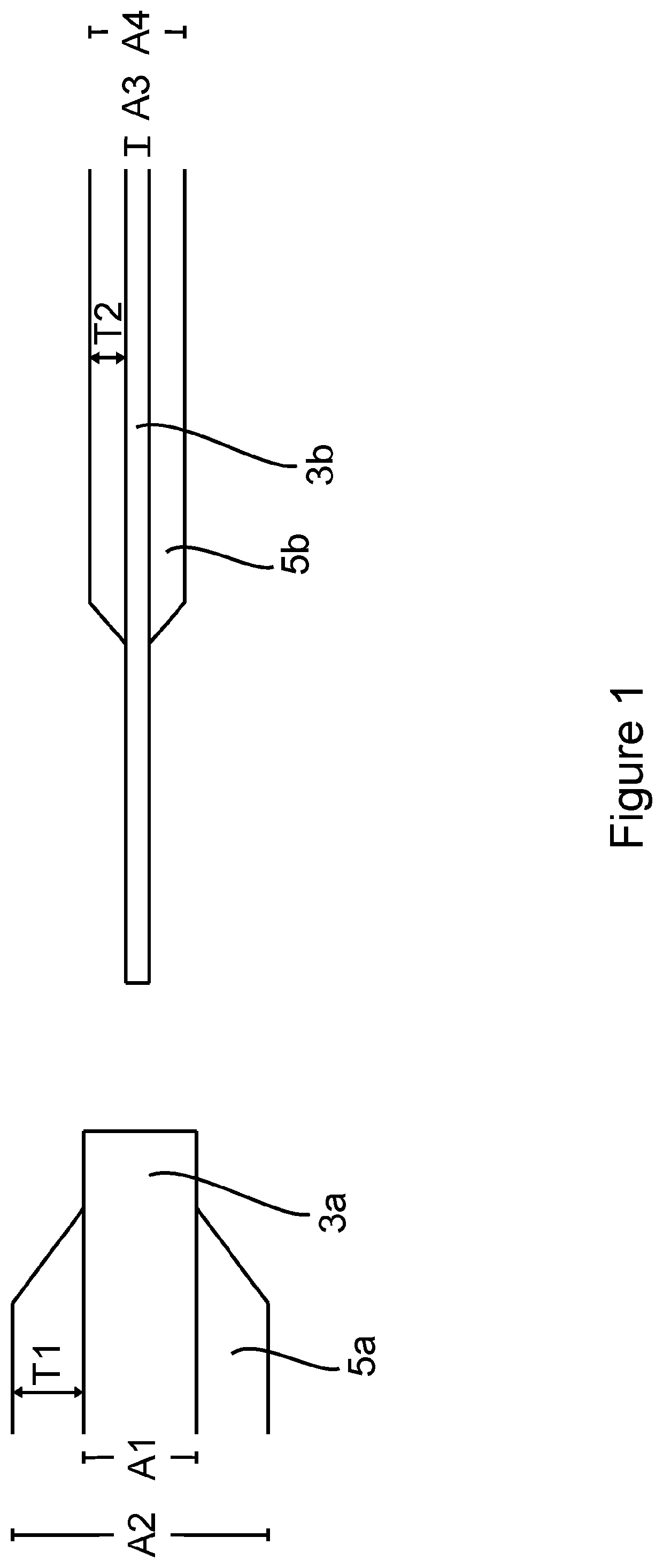
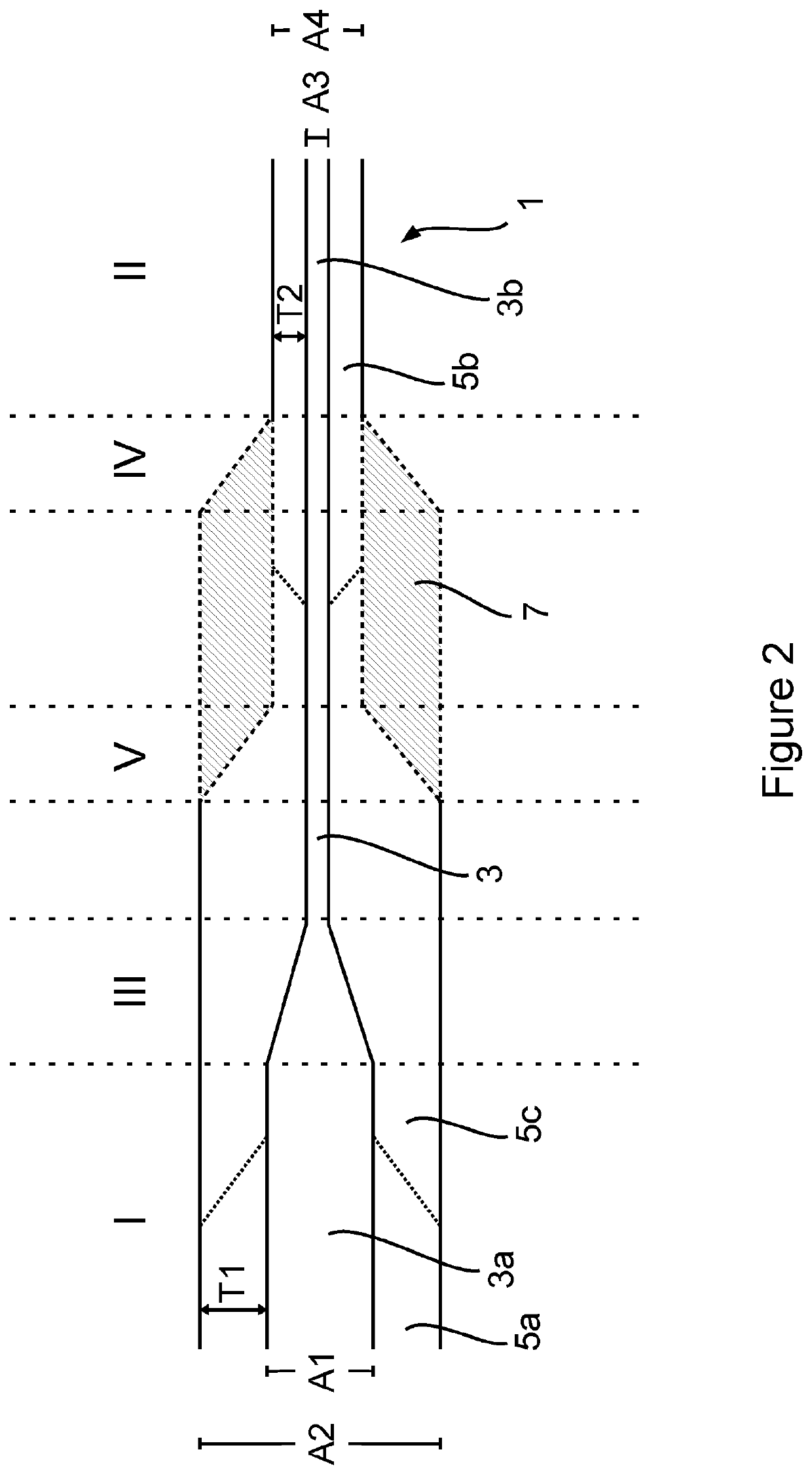
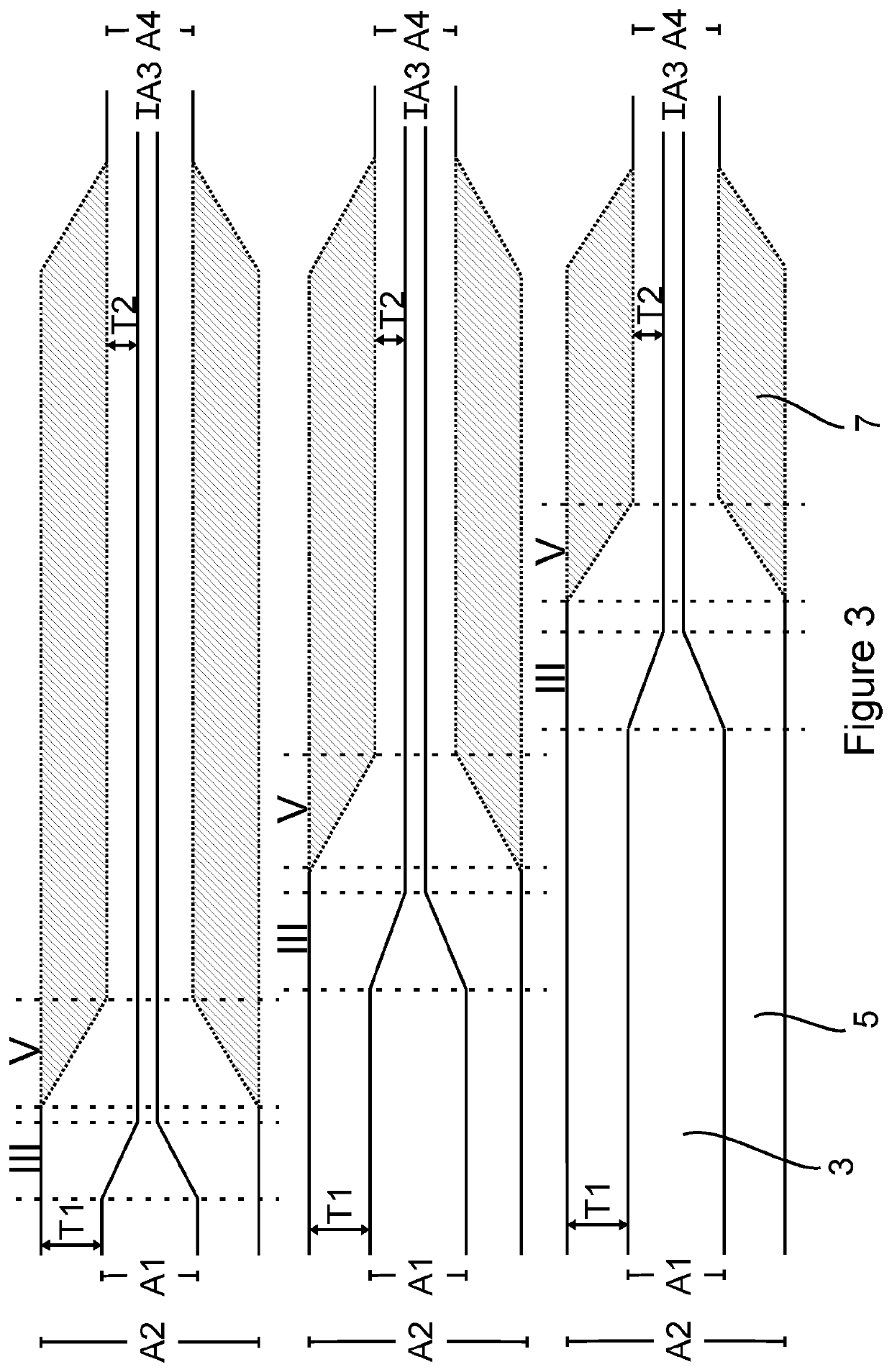
[0048]FIG. 1 schematically shows two separate sections of insulated cable. The first section of insulated cable (illustrated on the left-hand side of FIG. 1) includes a conductive core 3a (sometimes referred to as the conductor) and insulating material 5a surrounding the conductive core. The conductive core of the cable is usually made of a conductive metal but may be made from a non-metallic conductor such as carbon nano-tube technology. The conductive core 3a of the first section of insulated cable has a substantially constant cross-sectional area A1. The first section of insulated cable has a substantially constant overall cross-sectional area A2 and insulator thickness T1.

[0049]The second section of insulated cable (illustrated on the right-hand side of FIG. 1) also includes a conductive core 3b and insulating material 5b surrounding the conductive core. The core 3b of the second section of insulated cable has a substantially constant cross-sectional area A3, and the second sect...


PUM

PropertyMeasurementUnit
distanceaaaaaaaaaa
distanceaaaaaaaaaa
temperaturesaaaaaaaaaa

Abstract

The invention relates to insulated submarine cables including conductive cores (3a, 3b) and insulating material (5a, 5b) surrounding the conductive cores (3a, 3b). Such an insulated cable includes a first length and a second length. The cable has a roughly constant core (3a) cross-sectional area A1 and a roughly constant insulating material (5a) thickness T1 along the first length, and a different roughly constant core (3b) cross-sectional area A3 and / or a different roughly constant insulating material (5b) thickness T2 along the second length. The cable may include one or more other lengths which join the first length and the second length to one another.

Description

CROSS-REFERENCE TO RELATED APPLICATIONS[0001]The present application claims priority to PCT International Application No. PCT / GB2017 / 052149 filed on Jul. 21, 2017, which claims priority to GB1612689.8 filed Jul. 21, 2016, the entirety of the disclosures of which are expressly incorporated herein by reference.STATEMENT RE: FEDERALLY SPONSORED RESEARCH / DEVELOPMENT[0002]Not Applicable.FIELD OF THE INVENTION[0003]This invention relates to insulated cables. In particular, it relates to an insulated cable including a conductive core and insulating material surrounding the core, wherein the cable includes lengths having different core cross-sectional areas throughout its continuous length. The lengths may additionally or alternatively have different thicknesses of insulating material surrounding their respective cores throughout its continuous length.BACKGROUND OF THE INVENTION[0004]Insulated cables have applications in numerous fields. For example, insulated cables may be used in submarin...

Claims


Application Information

Patent Timeline
Patent Type & Authority Patents(United States)
IPC IPC(8): H01B7/14H02G1/14H01B3/44H01B7/282H02G9/00H02G15/18H02G15/14H02G1/10
CPCH01B7/14H01B3/441H01B7/282H02G1/14H02G9/00H02G1/10H02G15/14H02G15/18
Inventor SHROLL, PHILIPSTANLEY, MARKYOUNG, JAMESFEATHERSTONE, JEREMY
Owner JDR CABLE SYST
Why Eureka
Try Eureka