
Piezoelectric actuator type control device for capacitive loads

a technology of actuators and control devices, applied in the direction of device details, device details, generators/motors, etc., can solve the problems of limiting the use and development of actuators, affecting the performance of actuators, and affecting the use of actuators

Active Publication Date: 2022-06-07
CENT TECHN DES IND MECANIQUES +2
View PDF3 Cites 0 Cited by
  • Summary
  • Abstract
  • Description
  • Claims
  • Application Information

AI Technical Summary

Benefits of technology

The invention is a device for controlling a piezoelectric actuator using a control computer. The device includes a first stage for generating a DC voltage and a second stage for generating a variable excitation voltage for the actuator. The second stage includes two half-bridges of switches connected in parallel to the terminals of a bus capacitor. The control computer can control each half-bridge of switches independently or jointly as a full bridge. The device can be used to control a pair of piezoelectric actuators connected in a face-to-face assembly or a single actuator connected at the output of each half-bridge of switches. The control computer can also control the discharge resistor and the inductor connected at the output of the half-bridges of switches. The technical effect of the invention is to overcome the limitation of the conventional control method and achieve more precise and efficient control of piezoelectric actuators.

Problems solved by technology

However, the nonlinear effects which characterize their operation hold back their use and their development.
The supply of power to and the control of these actuations give rise to problems related to the capacitive nature of their impedance.
Their limited travel may also prove to be problematic, as is their fragility when they are subjected to anything other than compressive strain.
These two constraints, in combination with a requirement for compactness, are antagonistic by their nature, frequently resulting in performance limitations, increased bulk and / or high costs.
The drawback of this type of assembly lies in the fact that with the current full-bridge inverters, it is necessary to use a dedicated power electronics system per actuator, which increases the costs considerably.
One of the main problems is due to the fact that when voltage is applied to the system, if precautions are not taken beforehand, the actuator connected to the line at the high potential with a value Umax may be subjected to wildly varying voltages, depending on the DC voltage source (DC supply stage), which may result in faults.
The necessity of these precautions is further highlighted by another issue of note for these actuators, related to the relative tensile mechanical fragility.
However, inverters based on the half-bridge topology, which are broadly preferred because of their simplicity in terms of production and implementation, do not allow, with single-level DC voltage stages, negative voltages to be generated.
In other words, half-bridge inverters do not allow the possibility of exciting these actuators using negative voltages to be exploited.
Thus, it appears to be difficult to provide a common power electronics system that is capable of adjusting to the various operating modes mentioned.

Method used


Image

  • Piezoelectric actuator type control device for capacitive loads

Examples


Embodiment Construction

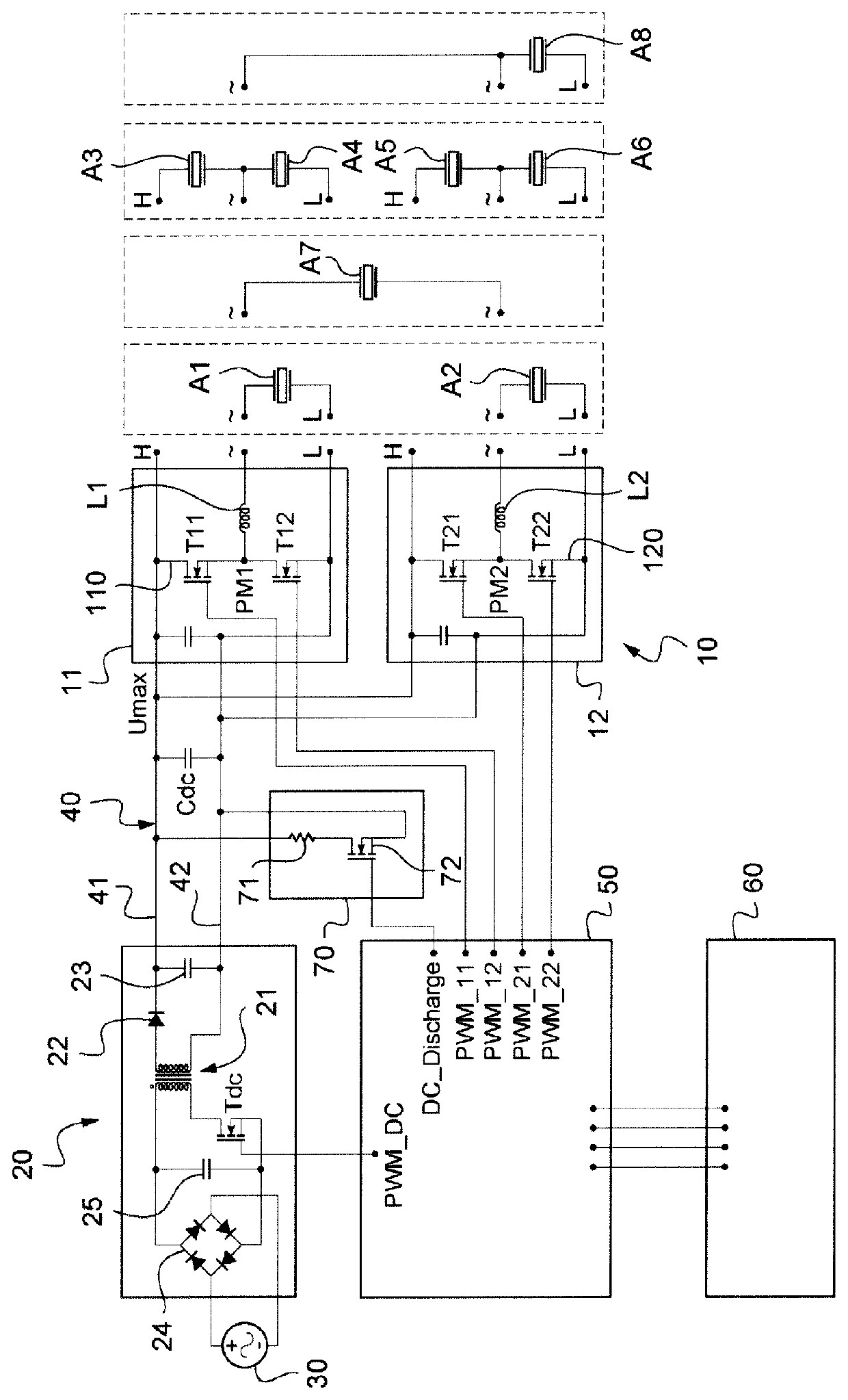
[0024]According to the diagram in the sole FIGURE, the control device of the invention comprises a DC-to-AC voltage converter circuit 10 suitable for driving one or more actuators according to various possible operating modes, which will be described in detail below. The DC-to-AC converter circuit 10 is designed to generate a periodic high voltage, which may reach many hundreds of volts, for example equal to 1000 V, at high frequency, which may reach, for example, several tens of kHz, in order to excite the one or more piezoelectric actuators, from a DC voltage source, in this instance an AC-to-DC voltage converter circuit 20. This converter circuit 20 is for example a flyback converter, which is one of the possible topologies for carrying out this function. It comprises a transformer 21 and a chopping transistor Tdc in series with the primary winding of the transformer 21, while a diode 22 and an output capacitor 23 are arranged at the output of the secondary winding of the transfo...


PUM


Abstract

A piezoelectric actuator control device comprising a first voltage converter supplying a DC voltage on a DC power supply bus to which is connected a second voltage converter capable of generating a variable excitation voltage under the control of a control computer, the second voltage converter comprising two switch half-bridges mounted in parallel with the terminals of a bus capacitor, the control computer being suitable for controlling the two switch half-bridges according to a first control configuration, in which they are controlled independently in order to each supply a voltage in a range between zero and a maximum positive value and according to a second control configuration, in which they are jointly controlled as a full-bridge for supplying a voltage between a minimum negative value and said maximum positive value.

Description

CROSS-REFERENCE TO RELATED APPLICATIONS[0001]The present application is a 35 U.S.C. §§ 371 national phase conversion of PCT / FR2017 / 053554, filed Dec. 13, 2017, which claims priority to French Patent Application No. 1662550, filed Dec. 15, 2016, the contents of which are incorporated herein by reference. The PCT International Application was published in the French language.TECHNICAL FIELD[0002]The present invention relates to a device for controlling at least one piezoelectric actuator driven electronically using a control computer.BACKGROUND OF THE INVENTION[0003]A certain number of applications requiring actuation means based on piezoelectric actuators are known.[0004]For example, in control applications, active movements of piezoelectric actuators, placed in judiciously chosen locations, may be controlled so as to counteract the effect of external interference, thus decreasing the amplitude of vibrations, of noise, etc.[0005]In other types of applications, for example in the fiel...

Claims


Application Information

Patent Timeline
Patent Type & Authority Patents(United States)
IPC IPC(8): H01L41/04H02N2/08H02M7/5387H02M11/00H02N2/06H10N30/80
CPCH01L41/042H02M7/5387H02M11/00H02N2/065H10N30/802
Inventor MASCIANTONIO, UGOMORARU, GEORGEDURDAN, THÉOPHILE
Owner CENT TECHN DES IND MECANIQUES
Learn More