
Magnetic logic device

a logic device and magnetic field technology, applied in the direction of logic circuits using saturable magnetic devices, magnetic bodies, pulse techniques, etc., can solve the problems of high-speed logic operation, high write in-plane current, and a limit in spin transfer torque of magnetic domain walls, etc., to achieve high magnetization inversion, low write in-plane current, and rapid switching operation

Active Publication Date: 2022-06-14
KOREA ADVANCED INST OF SCI & TECH
View PDF15 Cites 0 Cited by
  • Summary
  • Abstract
  • Description
  • Claims
  • Application Information

AI Technical Summary

Benefits of technology

The present invention provides a magnetic logic device that has faster switching, low write in-plane current and increased information write reliability. It uses spin orbit torque instead of a magnetic tunnel junction for information write operation, which prevents damage to the tunnel insulating layer. Additionally, it has a fast shift speed, making it suitable for rapid computation.

Problems solved by technology

However, the spin transfer torque has a limit in shift speed of a magnetic domain wall and a higher-speed logic operation is required.
Further, a write operation using the spin transfer torque causes damage to a tunnel insulation layer.

Method used


Image

  • Magnetic logic device
  • Magnetic logic device
  • Magnetic logic device

Examples


Embodiment Construction

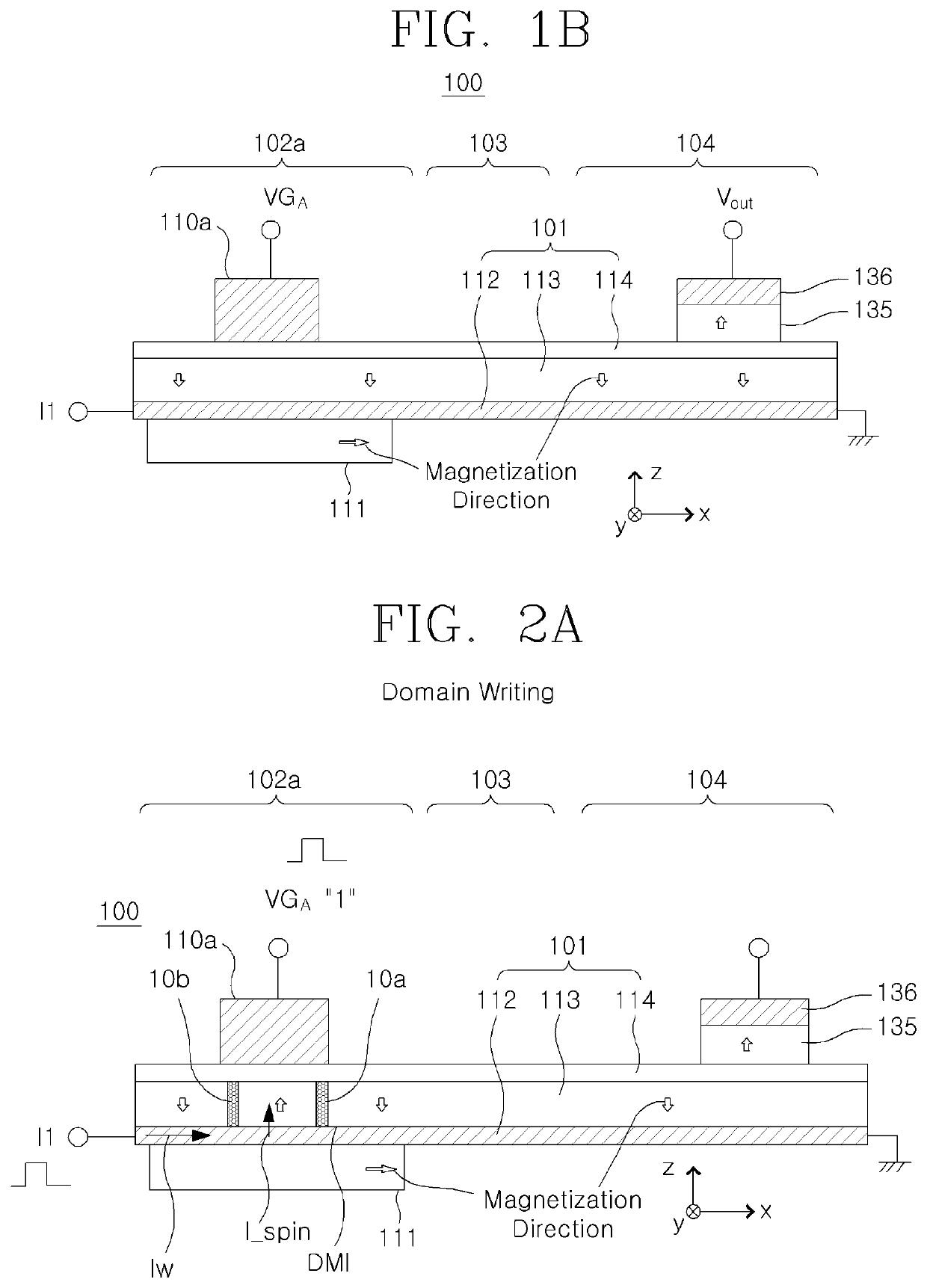
[0055]Perpendicular magnetic anisotropy (PMA) is a state in which spins are aligned in a perpendicular direction to a plane. In a ferromagnetic thin film structure having the perpendicular magnetic anisotropy, a domain in which a magnetization direction is aligned in a parallel or antiparallel direction of the perpendicular direction is referred to as a magnetic domain, and a boundary between the magnetic domains is referred to as a magnetic domain wall.

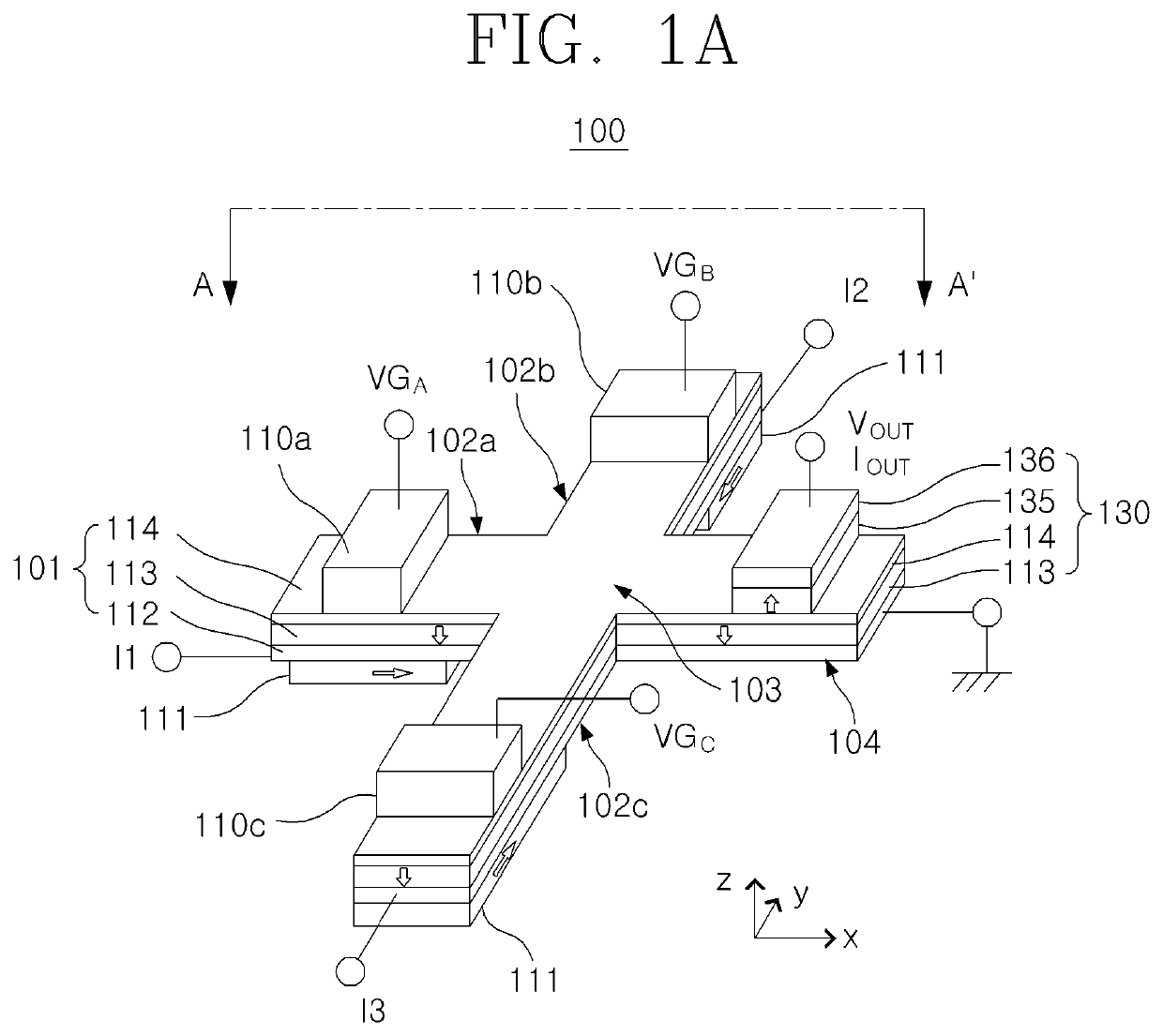
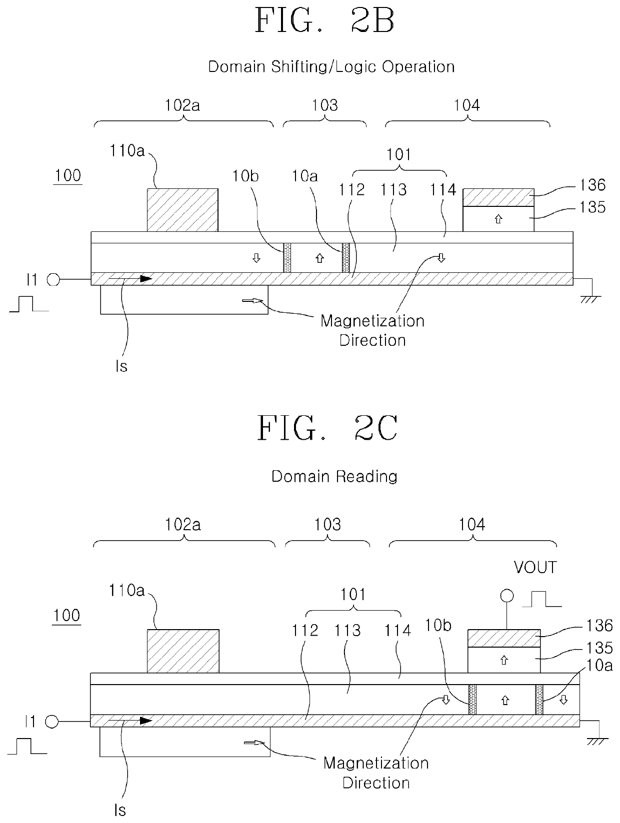
[0056]A magnetic logic device according to an exemplary embodiment of the present invention uses a magnetic nanowire having a non-magnetic metallic layer / free layer / insulating layer structure. The logic device includes a plurality of input branches receiving and writing external information; an output branch computing the written information and then outputting the computed information; and a coupling portion coupling the input branches and the output branch, and performing a logic operation. The logic device has a cross shape. A gat...


PUM

PropertyMeasurementUnit
speedaaaaaaaaaa
anisotropic ferromagneticaaaaaaaaaa
voltageaaaaaaaaaa

Abstract

Disclosed is a magnetic logic device including: a plurality of input branches configured by a magnetic nanowire including a non-magnetic metallic layer, a free layer, and an insulating layer sequentially stacked; an output branch configured by the magnetic nanowire; a coupling portion configured by the magnetic nanowire and where the input branches and the output branch meet; gate electrodes arranged adjacent to the insulating layer in each of the plurality of input branches; and in-plane anisotropic ferromagnetic layers arranged adjacent to the non-magnetic metallic layer in each of the plurality of input branches.

Description

CROSS-REFERENCE TO RELATED APPLICATION[0001]This application claims priority to Korean Patent Application No. 10-2020-0054160 filed May 7, 2020, the disclosure of which is hereby incorporated by reference in its entirety.BACKGROUND OF THE INVENTIONField of the Invention[0002]The present invention relates to a magnetic logic device, and more particularly, to a magnetic device that performs a logic operation by shifting a magnetic domain wall by using a spin orbit torque.Description of Related Art[0003]A typical magnetic majority gate logic device uses a cross-shaped magnetic nanowire. Three branches are used as an input and one branch is used as an output. (U.S. Pat. No. 10,236,046 B2) writes information on a magnetic domain by using a spin transfer torque by using a magnetic tunnel junction. Further, for a logic operation, the magnetic domain applies current to the magnetic nanowire and performs the logic operation while shifting by the spin transfer torque.[0004]However, the spin t...

Claims


Application Information

Patent Timeline
Patent Type & Authority Patents(United States)
IPC IPC(8): H03K19/16H01F10/32H03K19/20H10N50/10
CPCH03K19/16H01F10/3254H03K19/20H01F10/329H03K19/18H10N50/10
Inventor PARK, BYONG GUKKIM, KAB-JINLEE, GEUN-HEE
Owner KOREA ADVANCED INST OF SCI & TECH
Learn More