Data centre

a data centre and data technology, applied in the field of data centres, to achieve the effect of better and/or more efficient cooling

Active Publication Date: 2022-06-21
BRIPCO UK
View PDF6 Cites 0 Cited by
  • Summary
  • Abstract
  • Description
  • Claims
  • Application Information

AI Technical Summary

Benefits of technology

[0004]The present invention provides a data centre including one or more cold aisles and/or one or more hot aisles, and an access door providing access to at least one of the aisles, the door having an aperture in which is accommodated a controllable air intake arrangement. The door is movable between an open position allowing personnel access to the aisle and a closed position. In use of a data centre according to embodiments of the invention, cooling air flows via the doorway associated with the door, into or from the aisle when the door is in its closed position and the flow of air through the doorway, when the door is in its closed position, is controllable by means of the controllable air intake. In accordance with the present invention, the width of the door is wider than the width of the aisle. Given that the aisle will typically have a width that is substantially constant along its length, the door will therefore be wider than it needs to be in order to permit personnel access into/from the aisle. Indeed, having a door that is wider than the aisle will mean that in use the racks either side of the aisle will typically intrude into the doorway that is present when the door is open. However, in embodiments of the present invention, the concept of having a door that is wider than the aisle enables the aperture of the door to have a width that is larger than or substantially equal to the width of the aisle. This may enable the flow of air between the door (when closed, but with the air intake arrangement being fully open, for example) to be smoother as a result of the aperture hav

Problems solved by technology

Indeed, having a door that is wider than the aisle will mean that in use the racks either side of the aisle will typically intrude into the doorway that is present when the door is open.
The use of narrower vented doors (as proposed in WO2010139921 for example) may under certain operating conditions give rise to uneven distributio

Method used


Image

  • Data centre
  • Data centre
  • Data centre

Examples


first embodiment

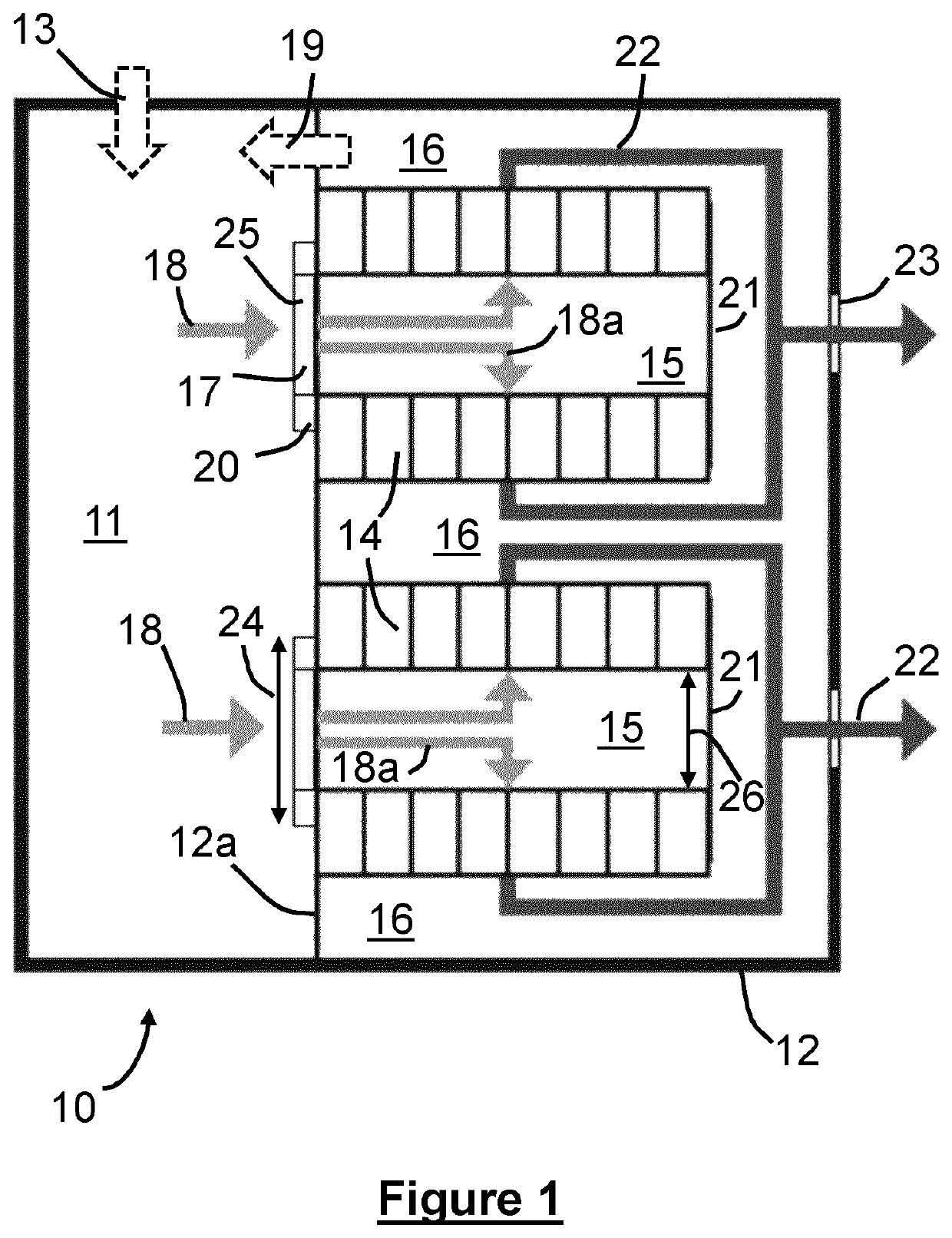
[0048]FIG. 1 shows a data centre building 10 according to the invention. The building 10 is rectangular with external walls 12. The building is divided into front and rear sections by an internal dividing wall 12a. The front section (on the right in FIG. 1) of the building 10 comprises four rows of racks 14. The racks 14 extend away from the internal dividing wall 12a, towards the front of the building. Although only shown schematically in FIG. 1, each rack in each row is in the form of an open fronted 42u standard universally compatible server rack. There are 20 such racks in each row, each rack typically housing up to 40 items of IT equipment (typically server blades). There may therefore be as many as 3,200 items of IT equipment in the racks in the building 10. A blanking panel 21 extends between the front ends of the first pair of rows of racks, thereby defining a cold aisle 15. A further blanking panel 21 extends between the front ends of the second pair of rows of racks, there...

second embodiment

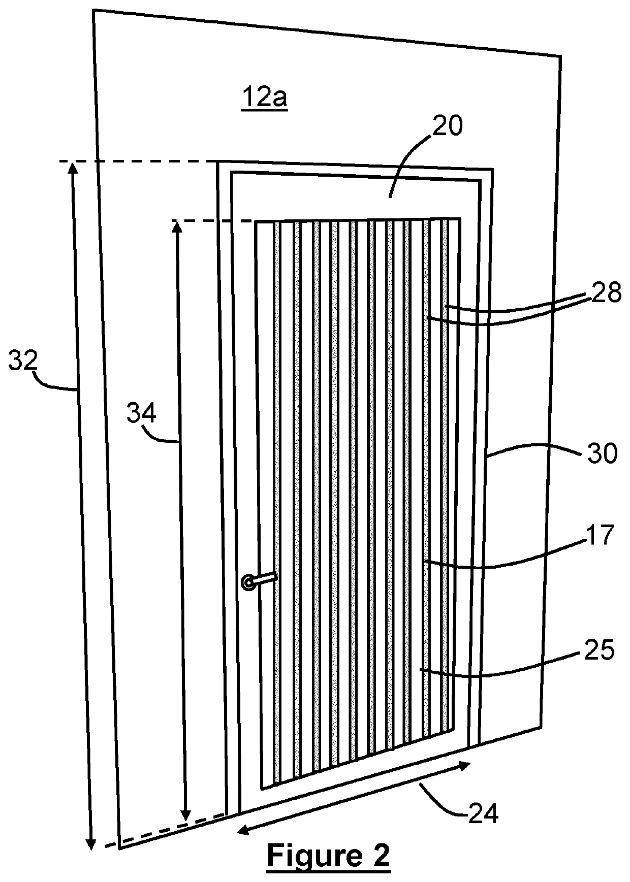
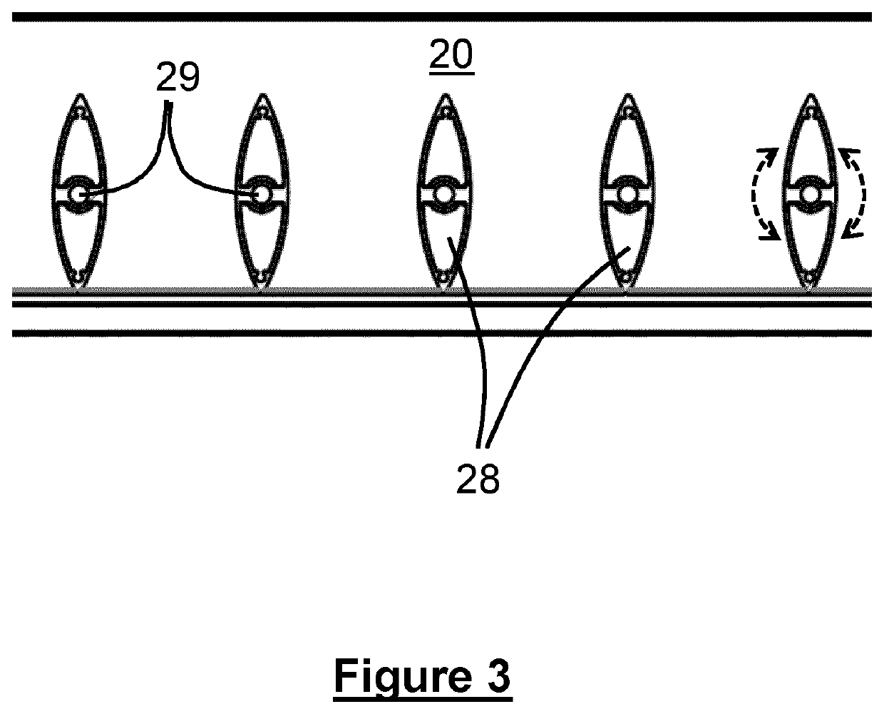
[0056]FIG. 5 shows a door 120 which is similar to that shown in FIG. 2, but is slightly larger and further includes a bar 140 for supporting the blades 128 of the venting arrangement 117. The door 120 of FIG. 5 also allows personnel access to the cold aisle whilst also providing a means for controlling airflow through the door, whilst the door is in its closed position (the position shown in FIG. 5). The door 120 includes a controllable vent arrangement 117 having a number of vertical blades 128 arranged in a row. The blades 128 are each mounted for rotation about a vertical axis, such that the vent may be moved between closed and open positions by means of rotation of the blades. FIG. 5 shows the blades 128 closer to the closed state (by way of a comparison with FIG. 2). The differences between the door of FIG. 5, as compared to the door of FIG. 2, will now be described. In this embodiment, the width 124 of the door is 1.4 m and the width of the aperture 125 in which the blades ar...

third embodiment

[0057]FIGS. 6 and 7 are hybrid views showing both (i) a rectangular data centre building 200 and (ii) a cold-aisle vented-door of the prior art to aid understanding. With reference to FIG. 6, there is shown a data centre building 200 having external walls 210 and which uses an indirect air cooling method for cooling the computer servers housed in the racks 214.

[0058]The IT racks 214 define three cold aisles 215 interleaved between four hot aisles 216. The cold aisles 215 are served with cooling air supplied by the indirect air optimiser unit 211 via a cold air corridor 233. The cooling air 218a enters each cold aisle 215, via the vents in the door 220 associated with that aisle. The cooling air 218a passes via the racks 214 to the hot aisles 216 and in the process cools the IT equipment in the racks 214. The resulting hot air 222 is then fed back to the air optimiser unit 211 as recirculated air 219. The received air 219 from the hot aisles 216 is cooled by means of a heat exchange...


PUM


Abstract

A data centre (10) includes one or more controllable air circulation systems (e.g. air optimiser (11)), one or more cold aisles (15) and/or one or more hot aisles (16), one or more rows of racks (14), the data centre being so arranged that in use cooling air (18) passes, under the control of the one or more controllable air circulation systems, from a cold aisle (15) through the racks (14) and/or through the racks (14) to a hot aisle (16). An access door (20), which provides access to at least one of the aisles, is movable between an open position allowing personnel access to the aisle and a closed position. The door (20) has an aperture (25) in which is provided a controllable air intake arrangement, for example comprising a vent (17) in the form of multiple vertically extending rotatable blades (28). The width (24) of the door is wider than the width (26) of the aisle associated with the door (20), so that the width of the aperture (25) may be larger than or substantially equal to the width (26) of the aisle. Air-flow into the aisle may therefore be subjected to less of a constriction than if the door (20) and aperture (25) were narrower.

Description

BACKGROUND OF THE INVENTION[0001]The present invention concerns data centres, a method of cooling equipment in a data centre and also subject matter ancillary thereto. More particularly, but not exclusively, this invention concerns data centre buildings having a hot aisle / cold aisle configuration and including at least one door for an aisle, wherein the door includes a controllable air intake arrangement accommodated in an aperture of the door. The invention also concerns such a door when provided by itself, a method of replacing a part of the controllable air intake arrangement of such a door, and a kit of parts for constructing a part of a data centre.[0002]WO2010139921 (corresponding to International Patent Application No PCT / GB2010 / 000759) discloses a data centre building having a hot aisle / cold aisle configuration and including a vented door for each cold aisle. The cooling of the data centre of WO2010139921 is effected by supplying cooling air under a regulated air pressure re...

Claims


Application Information

Patent Timeline
IPC IPC(8): H05K7/20B01D11/02A61K36/21A61K36/185A23L5/30A23L5/20E06B7/084
CPCH05K7/20A23L5/23A23L5/30A61K36/185A61K36/21B01D11/0288E06B7/084A61K2236/19A61K2236/333A61K2236/51A61K2236/53B01D11/0257H05K7/20745E06B7/09
Inventor THORNTON, WILLIAM
Owner BRIPCO UK
Why Eureka
Try Eureka