Methods, systems, and devices for vision testing

a technology of vision testing and system, applied in medical science, diagnostics, skiascopy, etc., can solve problems such as errors and variability, inability to know the location of visual stimulus, and inability to determine whether there is an eye instability

Active Publication Date: 2022-07-05
THE TRUSTEES OF INDIANA UNIV
View PDF3 Cites 0 Cited by
  • Summary
  • Abstract
  • Description
  • Claims
  • Application Information

AI Technical Summary

Benefits of technology

[0006]The present invention relates to methods, systems, and devices designed for diagnostic use by eye care providers and researchers in clinical trials to more accurately specify the visual function of an eye and the potential for improvement with treatment. The methods, systems, and devices achieve simplicity of operation, patient comfort, and efficiency. The methods, systems, and devices are suitable for providing the broad range of information needed to specify the causes of decreased vision, which impact on treatment decisions. The systems has several subsystems that together provide improved accuracy and can be manufactured at significantly less cost or provide better accuracy and efficiency than systems that perform only some of the functions of the subsystem. The device and system can readily interface with modern computer technology to augment the database used in decision making or transmit information to an external database for decision making for treatment decisions.
[0013]The present invention 3) identifies the optical errors of a patient's eye and are not limited to sphere and cylinder, but includes other optical errors resulting from pathological conditions or aging conditions found in the cornea, lens, or pupil, collected by wavefront sensor measurement of the light returning from the retina. These errors result from wavefront aberrations that lead to complex sources of blur on the retina, making it difficult to determine if reduced visual acuity is due to retinal disease vs. anterior segment issues such as cataract or poor tear film. Increased age has long been known to increase these optical errors that blur visual stimuli on a patient's retina, with the blur not readily remedied by merely adding sphere or cylinder corrections, such as those found in spectacles. See for instance how age-related changes in monochromatic wave aberrations of the human eye can be measured as reported by McLellan, J. S., Marcos, S., & Burns, S. A. (2001); Investigative ophthalmology &visual science, 42(6), 1390-1395. The present disclosure therefore provides one or more embodiments including method and / or apparatuses that emphasizes improving the characterization of factors underlying the visual performance or function in the aging eye, which reduces the cost and improves the accuracy of analyzing eye conditions.
[0014]The present invention 4) provides an objective correction with adaptive optics during the measurement of visual function of the main optical errors of a patient's eye, which is not limited to sphere and cylinder, using the wavefront measurements discussed above in item 3 above. The present invention also provides an estimate of the accuracy of the measurements leading to the correction and the expected success of the correction. This enables visual function tests to be performed using a beam of directed light that is precisely focused onto the retina, which provides a better and more complete result than can be achieved with just the standard correction of sphere and cylinder, or the habitual refraction that is often significantly in error when there is retinal elevation as the result of exudative eye disease. This feature is in essence an autorefractor that includes more than just sphere and cylinder, and provides even greater accuracy in when used in combination with the other features that are not found in an autorefractor.
[0018]It is well-known that consideration of the factors of visual stimuli including retinal eccentricity, which is the distance from the fovea, and contrast can improve the sensitivity of visual function testing, along with the specific algorithm, Hahn, G. A., Messias, A., Mackeben, M., Dietz, K., Horwath, K., Hyvärinen, L., Leinonen, M., & Trauzettel-Klosinski, S. (2009). Parafoveal letter recognition at reduced contrast in normal aging and in patients with risk factors for AMD. Graefe's archive for clinical and experimental ophthalmology—Albrecht von Graefes Archiv fur klinische und experimentelle Ophthalmologie, 247(1), 43-51. The distance from the fovea of a visual stimulus is quantified by retinal imaging. Measurement of contrast of a visual stimulus projected through the optics of the eye and on the retina is improved by the use of wavefront measurement. To reduce cost and complexity, computations from the retinal image, with or without structured illumination, can also be used to provide information about the contrast of a visual stimulus on the retina. Another method to reduce cost and complexity is to use the visual display as the illumination for the wavefront sensor. With the limited sensitivity of current sensors at present, NIR illumination is preferred for simultaneous measurement of contrast of visual stimulation on the retina during visual function measurements because visible wavelength illumination would have to be so bright was to interfere with a visual function task. However, in one or more of the disclosed embodiments, the visual display is used as the illumination source for estimating wavefront error, using alternation of the visual stimuli that have wavelengths in the visible range and the measurement of contrast by either a wavefront sensor or the retinal imaging method. In one or more embodiments, light of wavelengths shorter than near infrared (NIR) are used. In another embodiment, temporal modulation of the illumination for the wavefront sensor or the retinal image can also be used to provide frequency-based detection schemes to improve the signal-to-noise ratio. In other embodiments, more complex schemes of homodyne and heterodyne detection, based on frequency are used to improve signal-to-noise ratio.
[0020]The present invention 5) projects a visual target onto the retina through a fixed size pupil of the instrument to reduce the enormous variability due to individual differences in the size of a patient's natural pupil, when compared with an ideal pupil size or based on the amount of light reaching the retina through the pupil.

Problems solved by technology

Errors and variability are a direct result of these artifacts and cannot be overcome merely with software or algorithms, of which many have been proposed that address specific stimuli or optotype; algorithm for stimulus presentation; or testing factors such as patient fatigue, the criterion used by the patient, or cognitive deficits.
Without retinal imaging that is approximately video rate or faster, it is not possible to know the location of the visual stimulus with respect to the status of the retina, since the human eye moves frequently.
Further, without retinal imaging that is relatively fast with respect to eye movements, it is not possible to determine whether there is an instability of the eye, and whether the visual target is smeared across the retina or whether the eye is in position long enough to permit detection or recognition of a visual target.

Method used


Image

  • Methods, systems, and devices for vision testing
  • Methods, systems, and devices for vision testing
  • Methods, systems, and devices for vision testing

Examples


Embodiment Construction

[0036]The embodiments of the present invention described below are not intended to be exhaustive or to limit the invention to the precise forms disclosed in the following detailed description. Rather, the embodiments are chosen and described so that others skilled in the art may appreciate and understand the principles and practices of the present invention.

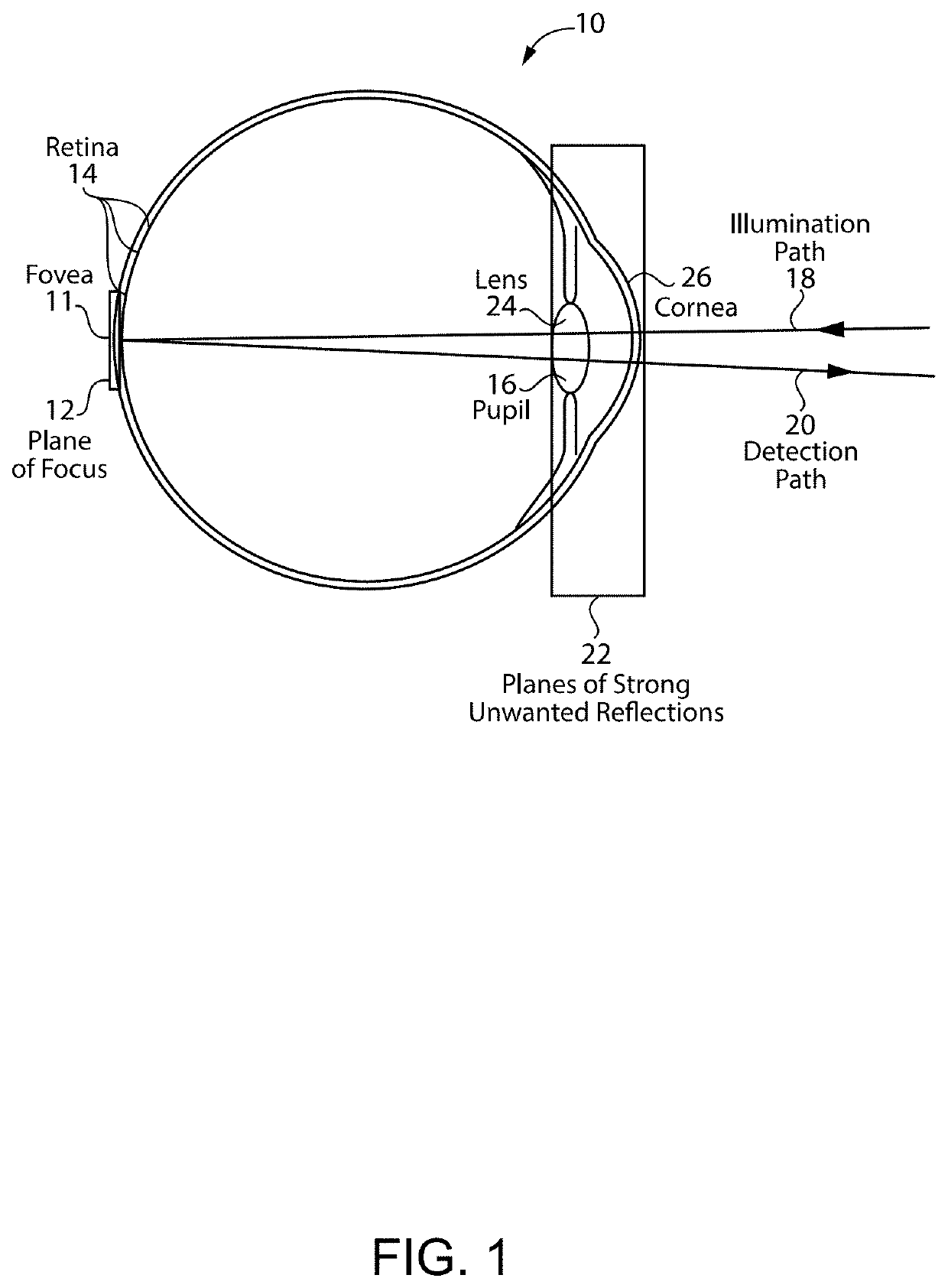
[0037]FIG. 1 illustrates a schematic diagram of an eye 10 showing selected tissues including a pupil 16 through which light from a light source provides a visual stimuli, such as a visual display, is projected, a retinal plane 12 as the target plane of focus for the projection of visual stimuli and imaging of retinal and subretinal structures, a cornea 26, a lens 24, and other anterior segment structures. As used herein, “visual display” is used to describe a device that transmits a visible or non-visible light image directed toward and received by the eye of a patient. Once received by the eye, the patient undertakes tasks that ...


PUM


Abstract

Methods, systems, and devices to improve the assessment of visual function and overcoming limitations of current methods to identify the visual function that potentially could be reached by a given eye. Multiple eye tests including visual stimuli plus optical measurement components, and methods to combine the results, identify and quantify sources of decreased vision resulting from optical sources, such as a lens and cornea as distinguished from retinal sources. By identifying potentially correctable optical sources of decreased vision, and overcoming physiological limitations such as size of the eye's pupil, the visual benefits of treatment such as by cataract or corneal surgery are distinguished from retinal pathology that requires medical intervention. The devices and methods provide metrics that include an expected value of the visual function and sources of variability including both optical and neural components, to guide treatment and improve clinical trials.

Description

STATEMENT REGARDING FEDERALLY SPONSORED RESEARCH OR DEVELOPMENT[0001]This invention was made with government support under EY030829 awarded by the National Institutes of Health. The Government has certain rights in the invention.BACKGROUND OF THE INVENTION[0002]Visual acuity and other visual functions guide the management of patients with retinal diseases and conditions. Such tests of visual function also serve as endpoints for clinical trials to investigate treatments. While printed and electronic charts to measure visual acuity or other visual functions are commonly used because they are standardized, easy to use, and can be widely distributed, they are inaccurate for the purpose of evaluating the status of the retina. Such charts fail to minimize or quantify factors that degrade eye performance due to optical factors such as stray light, poor transmission, and lack of sharp focus due to problems with the eye's tear film, cornea, or lens.[0003]Additional optical factors include, b...

Claims


Application Information

Patent Timeline
Patent Type & Authority Patents(United States)
IPC IPC(8): A61B3/10A61B3/14A61B3/00A61B3/028
CPCA61B3/1015A61B3/0008A61B3/0025A61B3/028A61B3/101A61B3/1025A61B3/103A61B3/12
Inventor ELSNER, ANN E.
Owner THE TRUSTEES OF INDIANA UNIV
Why Eureka
Try Eureka