Thermophysical float glass process

Active Publication Date: 2022-07-19
MASTEN JR JAMES W
View PDF16 Cites 0 Cited by
  • Summary
  • Abstract
  • Description
  • Claims
  • Application Information

AI Technical Summary

Problems solved by technology

This pulling process creates significant stress on the glass, causing strain deformation within the glass.
The glass must go through a significant annealing process in order to relieve the strain which, if not removed, affects the optical clarity of the glass and render

Method used


Image

  • Thermophysical float glass process
  • Thermophysical float glass process
  • Thermophysical float glass process

Examples


Embodiment Construction

[0030]The following list provides specific descriptions and examples of items that are present in the embodiments illustrated by the figures. The descriptions in the list are illustrative of specific embodiments, and should not be construed as limiting the scope of this disclosure.

REFERENCE

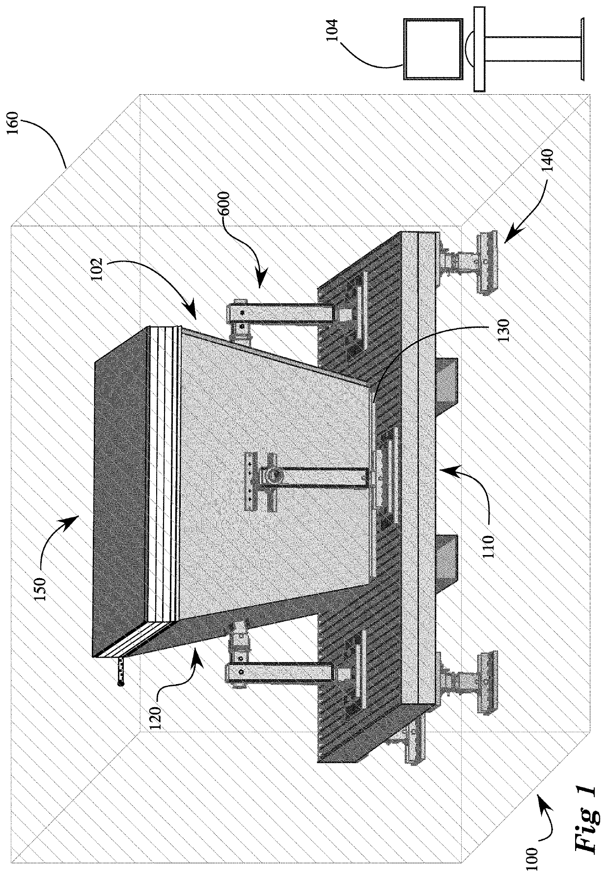
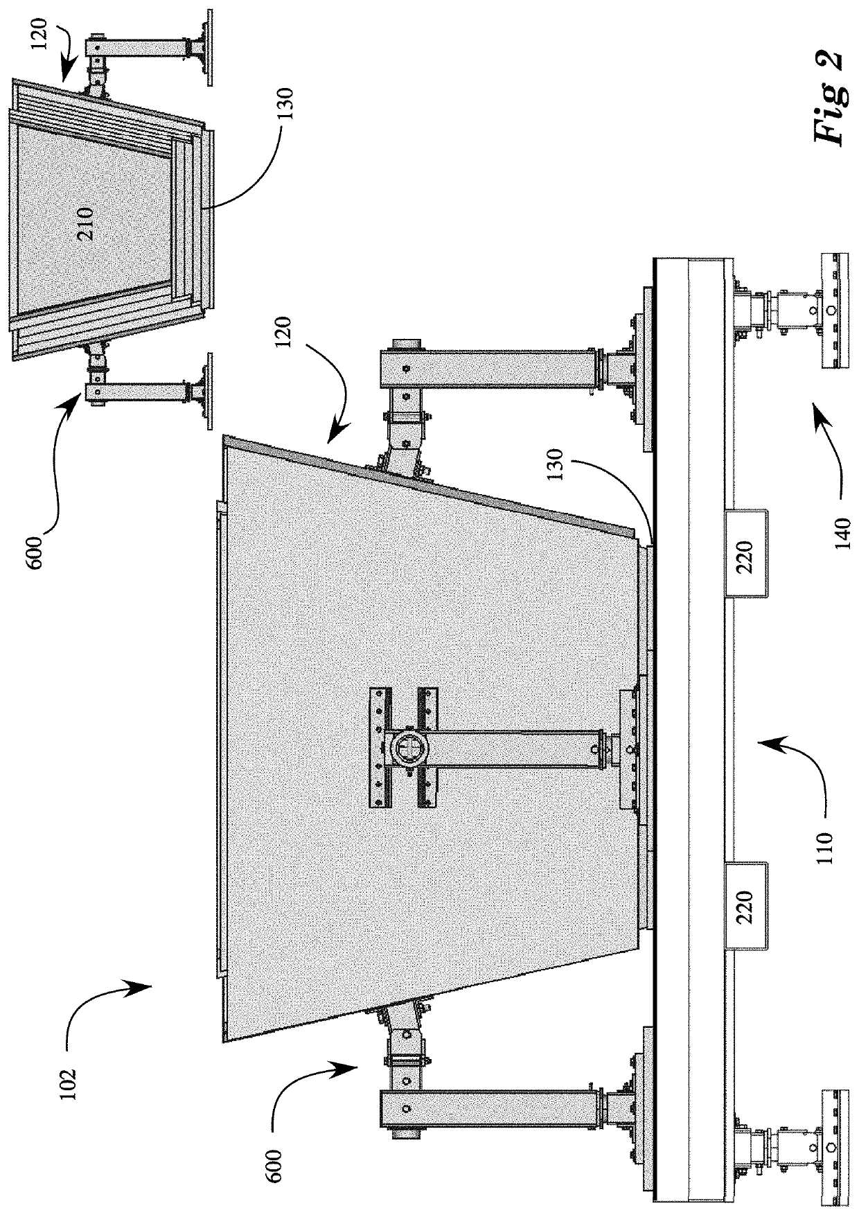
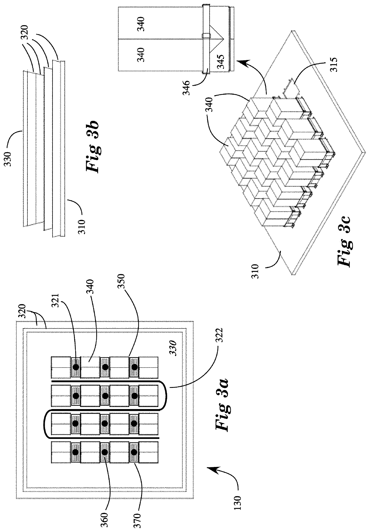
[0031]Numerals Description[0032]100 Float glass system[0033]102 Tank[0034]104 Controller[0035]110 Tank platform[0036]120 Tank side assembly[0037]130 Tank bottom assembly[0038]140 Tank platform load cell foot[0039]150 Tank roof or top cover assembly[0040]160 Environmental chamber[0041]210 Tub[0042]220 Forklift pocket[0043]310 Bottom plate[0044]315 Shallow placement pocket in bottom plate[0045]320 Bottom refractory layer[0046]321 Cooling gas jet in tank bottom assembly[0047]322 Fluid channel in tank bottom assembly[0048]330 Innermost bottom refractory layer[0049]340 Insulating brick[0050]345 Sheet metal wrap forming hollow pocket to hold insulating brick[0051]346 Sheet metal band or retainer[0052]35...


PUM

PropertyMeasurementUnit
Temperatureaaaaaaaaaa

Abstract

A novel apparatus and method for producing flat glass by floating molten glass on liquid tin, significantly improving the efficiency of heating the tin and reducing or eliminating the need to anneal by eliminating the stress introduced by pulling the glass across the tin bath. The apparatus directly heats and melts the tin by exposure to high-intensity infrared energy through surfaces of the tin-containing tub, said tub made from a material that is transmissive at selected infrared wavelengths.

Description

BACKGROUND[0001]Near the middle of the twentieth century, a process was developed to make glass nearly perfectly flat by pouring the liquid glass on liquid tin. Liquids at rest near the surface of the earth take on the surface curvature of the earth, as can be recognized by the distance to the horizon on the ocean or large lakes. Because tin is denser than glass, the glass floats on the tin and spreads out to be nearly perfectly flat, with the top of the glass and the bottom of the glass nearly perfectly parallel. For a float line, a glass furnace is typically on the order of −150 ft long by 30 ft wide and holds around 1200 tons of glass. To achieve chemical homogeneity, the glass is heated to about 1550-1600° C. in the furnace, and brought to about 1100-1200° C. in a forehearth. From there, the glass flows through a channel onto a tin bath that is maintained at a temperature of 600° C.[0002]Because tin remains liquid at temperatures at which glass has become a solid, the glass is a...

Claims


Application Information

Patent Timeline
IPC IPC(8): C03B18/18C03B27/03C03B25/02C03B18/20
CPCC03B18/18C03B18/20C03B25/025C03B27/03C03B18/16C03B18/22
Inventor MASTEN, JR., JAMES W.
Owner MASTEN JR JAMES W
Why Eureka
Try Eureka