Wireless power transfer control

a technology of power transfer and control, which is applied in the direction of transportation and packaging, safety/protection circuits, and lifts, etc., can solve the problems of connector wearout within weeks, difficult handling of charging cables, and fast wear of connectors

Active Publication Date: 2022-08-16
DELTA ELECTRONICS (THAILAND) PUBLIC CO LTD
View PDF17 Cites 0 Cited by
  • Summary
  • Abstract
  • Description
  • Claims
  • Application Information

AI Technical Summary

Benefits of technology

[0015]By independently of each other controlling the frequency and the voltage or the current of the AC primary output, the controlling of the power transferred becomes much easier than in the prior art. By controlling the frequency of the AC primary output to be substantially held at the resonance frequency, the power transfer is easily controlled just by changing the voltage or the current of the AC primary output to achieve the target power output of the AC secondary output to meet for example a target output current. When the primary and the secondary pad change their mutual position, their inductances and also their resonance frequency changes too. So, by controlling the frequency such as to keep the system at resonance, the transfer function of the system is not affected by such a position change and therefore the transferred power can be controlled easily and independently of the frequency control by just controlling the voltage or the current.
[0017]Due to the easier control, the power transfer capability of the system is not or at least less limited wherefore no or less oversizing of the system is necessary. Hence, no extra costs, no extra space and no extra time and effort are required.
[0031]In order to achieve an efficient operation of an inverter, soft-switching is used to switch the switches in the inverter. Accordingly, the frequency control is done by making sure that the voltage and the current of the AC primary output do have that minimum phase angle. By choosing the minimum phase angle properly, switching losses and EMI can be reduced or even minimised and it can be avoided that the parasitic capacitance of the primary resonator starts oscillating.
[0034]Or in other words, the primary voltage is proportional to the secondary current and the primary current is proportional to the secondary voltage. Hence controlling the power transferred from the primary to the secondary is rather simple by controlling either the current or the voltage of the AC primary output.
[0049]In another preferred embodiment of the invention, the secondary side therefore includes an overvoltage detector for detecting an overvoltage on the secondary side. And the secondary side is adapted to controllably shorten the secondary resonator in response to an overvoltage detected by the overvoltage detector. When the secondary resonator is shorted the resonance frequency in the primary changes in an instant. This is because when the secondary resonator is shorted, its flux guiding element is taken away which immediately changes the inductance of the primary coil because the part of the magnetic reluctance of the primary resonator formed by the secondary flux guiding element is missing. This change of resonance frequency can be detected in the primary. Once a shorted secondary resonator is detected, the inverter or converter in the primary is shut down to stop operation of the wireless power transfer arrangement and prevent further damage.
[0057]But in a preferred embodiment of the invention, the primary side includes a jump detector adapted to detect a short of the secondary resonator by detecting a jump of the resonance frequency of the primary resonator. As mentioned above, the resonance frequency in the primary changes when the secondary resonator is shorted. Such a change or jump of the resonance frequency or period respectively then is detected by the jump detector, for example by regularly measuring the frequency or the period of the primary voltage or current and comparing the measured frequency or period and declaring a jump of the resonance frequency if the difference of two successive measurements exceeds a given threshold. In this way, a jump of the resonance frequency can be detected very fast. The jump detector is preferably adapted to detect a jump of a period of the resonance frequency that is greater than 1000 nanoseconds and more preferably by detecting a jump of the period of the resonance frequency that is greater than 300 nanoseconds. In a most preferred embodiment of the invention the jump detector is adapted to detect a jump of a period of the resonance frequency that is greater than 100 ns. With a frequency of about 50 kHz a short in the secondary can preferably be detected within about 20 μs.

Problems solved by technology

The high charging currents with Li-Ion batteries may however cause problems with a wire-based charger where the charging current is fed from the power source to the battery via a cable connection where the cable is connected to the source and / or the battery by connectors.
Accordingly, the charging cables are difficult to handle and the connectors would wear out fast.
With an occasional charging such connectors would wear out within weeks.
Accordingly, these dependencies make the control of such a system more difficult or even limit the power transfer capability of the system, wherefore the system margins are usually increased to overcome such limitations.
But such an oversizing usually requires extra costs, extra space and extra time and effort.
Accordingly, the desired power output of the power converter is controlled by controlling the frequency of the inverter output and by controlling the duty cycle of the power converter which makes it difficult to correctly and efficiently control the power transferred and the battery charging current.

Method used


Image

  • Wireless power transfer control
  • Wireless power transfer control
  • Wireless power transfer control

Examples


Embodiment Construction

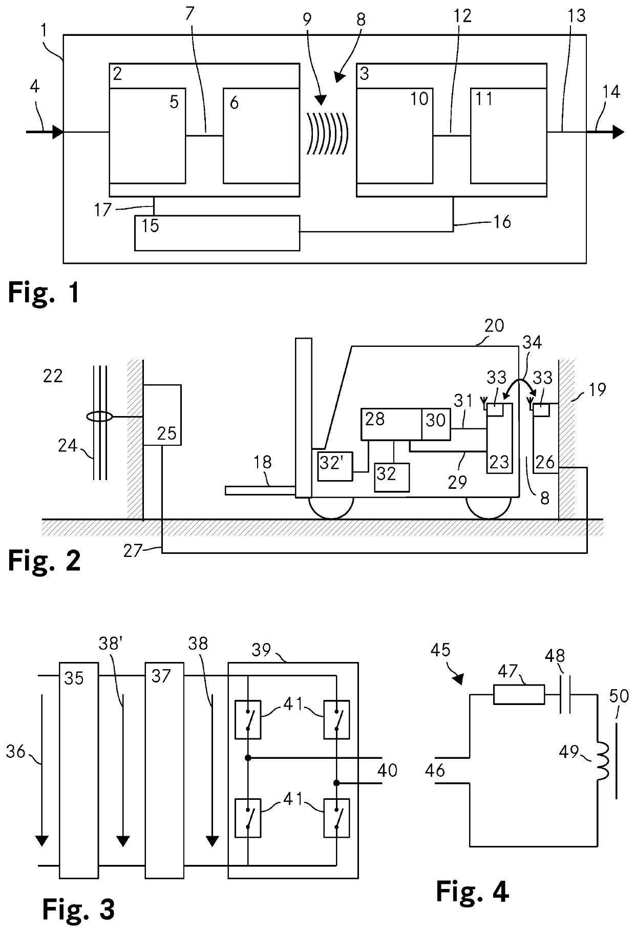
[0090]FIG. 1 shows a schematic representation of a first embodiment of a wireless power transfer arrangement 1 according to the invention. The wireless power transfer arrangement 1 includes a primary side 2, a secondary side 3 and a controller 15 which is shown to be separated from the primary side 2 and the secondary side 3. The primary side 2 includes an input stage 5 for converting an input power 4 into an AC primary output power 7 which is fed to a primary resonator 6. The primary resonator 6 induces a magnetic field 9 to wirelessly transmit power across an airgap 8. The secondary side 3 includes a secondary resonator 10 which picks up the magnetic field 9 and converts the power received through the magnetic field 9 into an AC secondary output 12. An output stage 11 is connected to the secondary resonator 10 and converts the AC secondary output 12 to a DC secondary output 13 which is then provided at an output of the wireless power transfer arrangement 1 as an output power 14.

[0...


PUM


Abstract

The invention concerns a wireless power transfer arrangement (1) including a primary side (2) and a secondary side (3) where the primary side includes an input stage (5) for converting an input power to an AC primary output and a primary resonator (6) for receiving the AC primary output and inducing a magnetic field (9) for wireless power transfer through an air gap (8). The secondary side (3) includes a secondary resonator (10) for converting the power received through the magnetic field (9) to an AC secondary output and an output stage (11) for converting the AC secondary output to a DC secondary output. A controller (15) is adapted to control independently of each other a frequency of the AC primary output to be at a resonance frequency of the resonators and the power transferred from the primary side (2) to the secondary side (3) by controlling the voltage or the current of the AC primary output. By locking the frequency of the system to the resonance frequency enables any easy power control simply by controlling the current or the voltage of the primary resonator (5).

Description

TECHNICAL FIELD[0001]The invention relates to a wireless power transfer arrangement including a primary side and a secondary side, the primary side including an input stage for converting an input power to an AC primary output and a primary resonator for receiving the AC primary output and inducing a magnetic field for wireless power transfer, the secondary side including a secondary resonator for converting the power received through the magnetic field to an AC secondary output and an output stage for converting the AC secondary output to a DC secondary output. The invention further relates to a primary arrangement with a primary side of such a charging arrangement, a secondary arrangement with a secondary side of such a charging arrangement and an automotive vehicle including such a secondary arrangement.BACKGROUND ART[0002]Electrical energy is used in many different applications. To power electrically driven devices, items or objects that are not permanently connected to a source...

Claims


Application Information

Patent Timeline
Patent Type & Authority Patents(United States)
IPC IPC(8): B60L53/12H02J50/12H02J7/00H02J50/80
CPCH02J50/12B60L53/12H02J7/00H02J7/0026H02J50/80H02J7/025H02J50/00B66B7/00Y02T10/70Y02T10/7072Y02T90/14H02J7/0029
Inventor RICHTER, ULRICH
Owner DELTA ELECTRONICS (THAILAND) PUBLIC CO LTD
Why Eureka
Try Eureka