Neuromorphic system
a neuromorphic system and neuromorphic technology, applied in the field of neuromorphic systems, can solve the problems of increasing power consumption, increasing heat release problems, and affecting the development of the entire area
- Summary
- Abstract
- Description
- Claims
- Application Information
AI Technical Summary
Benefits of technology
Problems solved by technology
Method used
Image
Examples
second embodiment
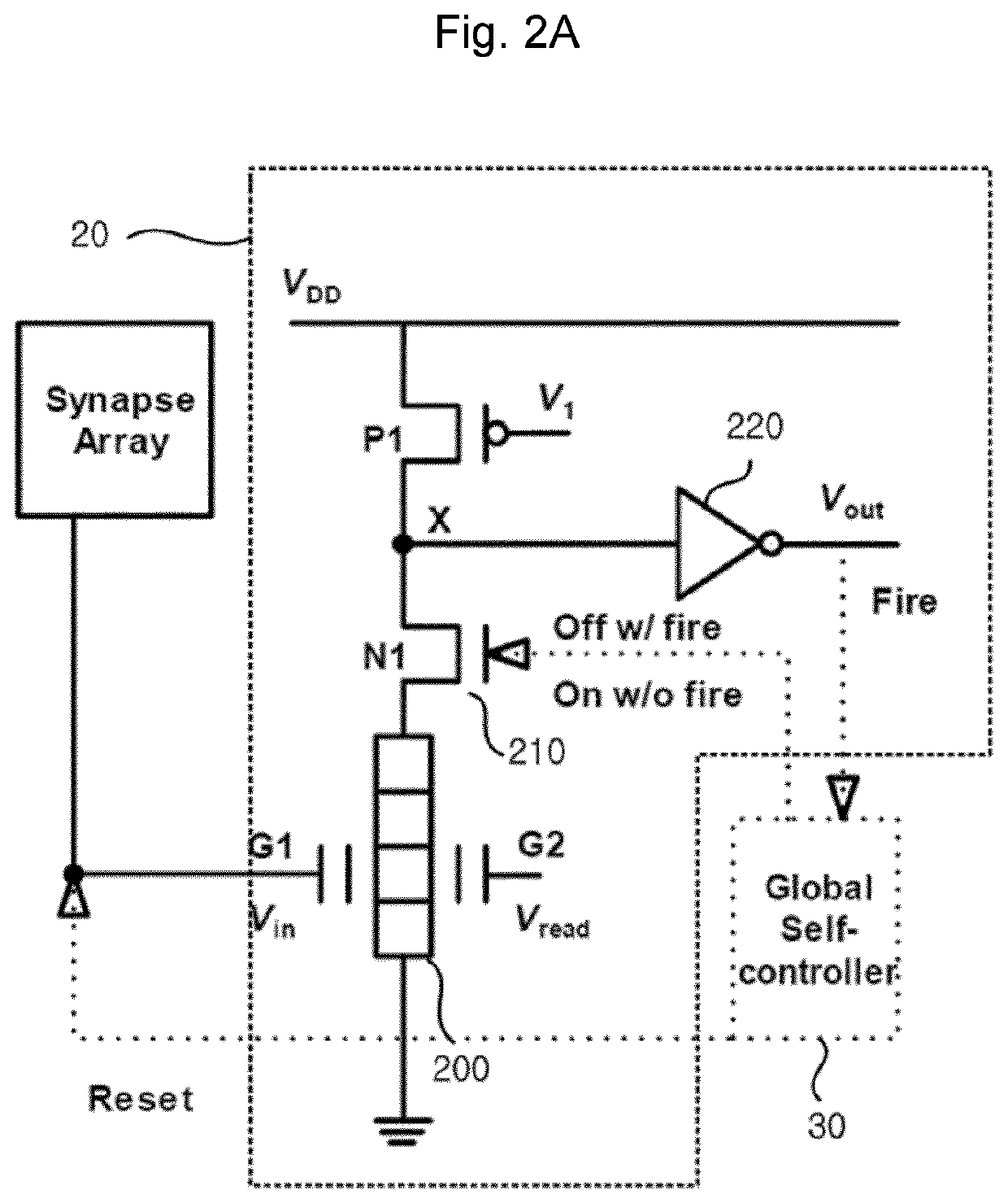
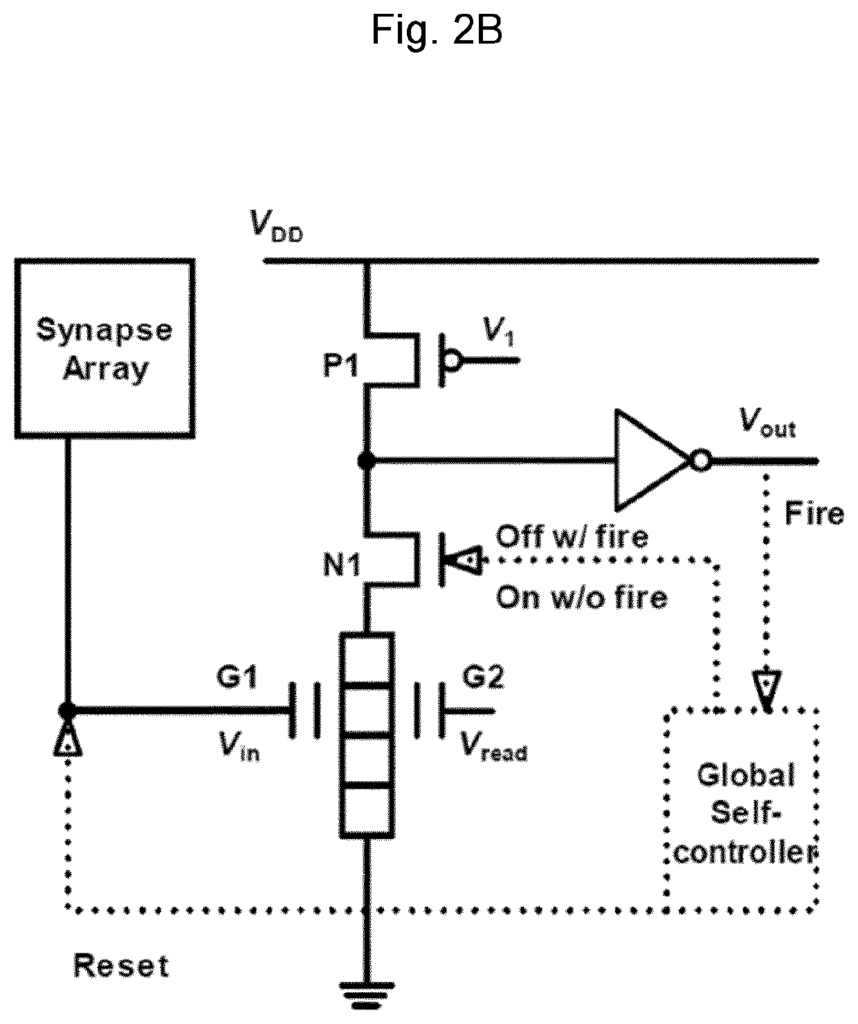
[0071]Hereinafter, the operation of the neuron circuit will be described.
[0072]When the current flows in the neuromorphic device to lower the potential of the node X, the potential of the output terminal is increased by the output circuit INV1, so that a current also flows in the second switch N2 to form a boosting path. As a result, the potential of the node X is more speedily lowered, and the firing occurs at a faster rate. The signal is transmitted to the p-MOSFET by the feedback circuit 230, and thus, P1 is turned on and the first switch N1 is turned off, so that the potential of the node X is increased to the voltage VDD again and the neuromorphic device is rest.
[0073]FIG. 4 is a circuit diagram of a neuron circuit according to a third embodiment of the invention. Referring to FIG. 4, a neuron circuit 24 according to the third embodiment is similar to the neuron circuit according to the second embodiment except that a third switch N3250 connected in series to the second switch...
third embodiment
[0075]Hereinafter, operations of the neuron circuit will be described. When the current flows in the neuromorphic device to lower the potential of the node X, the potential of the output terminal is increased by the output circuit INV1, so that a current also flows in the second switch N2 to form a boosting path. As a result, the potential of the node X is more speedily lowered, and the firing occurs at a faster rate. The p-MOSFET P1 is turned on by the feedback circuit, and at the same time, the third switch N3 is turned off to instantaneously prevent current from flowing in the second switch N2. The first switch N1 is turned off by the signal output from the global self-controller, the potential of the node X is stably increased to the voltage VDD again, and the neuromorphic device is reset.
first embodiment
[0076]FIG. 5 is a graph of voltage versus time illustrating operation characteristics of the neuron circuit in the neuromorphic system according to the invention.
[0077]Referring to FIG. 5, in the neuron circuit according to the invention, (a) illustrates a signal Vin input to the first gate electrode of the neuromorphic device as a signal pulse continuously output from the synapse array. (b) illustrates an output voltage Vout of the output circuit of the neuron circuit. When the signal pulse Vin from the synapse array is continuously input to the first gate electrode G1 of the neuromorphic device and the charges are accumulated and exceeds the predetermined threshold value, the voltage of the first gate electrode of the neuromorphic device is increased, and thus, the device operates as a positive feedback device, so that a current flows in the neuromorphic device and the potential of the node X is decreased. As a result, the voltage Vout of the output circuit is increased, and the f...
PUM
 Abstract
Description
Claims
Application Information
 - R&D
- Intellectual Property
- Life Sciences
- Materials
- Tech Scout
- Unparalleled Data Quality
- Higher Quality Content
- 60% Fewer Hallucinations
Browse by: Latest US Patents, China's latest patents, Technical Efficacy Thesaurus, Application Domain, Technology Topic, Popular Technical Reports.
© 2025 PatSnap. All rights reserved.Legal|Privacy policy|Modern Slavery Act Transparency Statement|Sitemap|About US| Contact US: help@patsnap.com


