
Increasing performance of a receive pipeline of a radar with memory optimization

a technology of memory optimization and receive pipeline, which is applied in the field of radar systems, can solve the problems of large memory requirements of high-resolution radar systems, and difficult to achieve high-resolution radar systems. achieve the effect of improving the performance of radar systems, reducing bit-width, and large memory requirements

Active Publication Date: 2022-09-27
UHNDER INC
View PDF386 Cites 0 Cited by
  • Summary
  • Abstract
  • Description
  • Claims
  • Application Information

AI Technical Summary

Benefits of technology

The present invention provides methods and apparatus to improve the performance of a radar system. The invention optimizes the storage and access of radar data cubes generated by Doppler and angle processing in the radar system. The invention categorizes regions of the radar data cubes, thresholding values to sparsify the data, optimizing DRAM access patterns, adding error detecting or error correcting bits, and storing the sparsified versions of the radar data cubes to memory for subsequent processing. The invention also includes maximizing DRAM read performance by burst locality by preserving access to data from multiple receivers. The technical effects of the invention include reducing the memory requirement for storing radar data cubes and optimizing radar system performance.

Problems solved by technology

This may require a very large amount of memory for high resolution radar systems.
This may also take a long time to transfer externally to an integrated circuit (off-chip memory).
The storage of large blocks of data in memory (such as the storage of RDCs) is also prone to errors.

Method used


Image

  • Increasing performance of a receive pipeline of a radar with memory optimization
  • Increasing performance of a receive pipeline of a radar with memory optimization
  • Increasing performance of a receive pipeline of a radar with memory optimization

Examples


Embodiment Construction

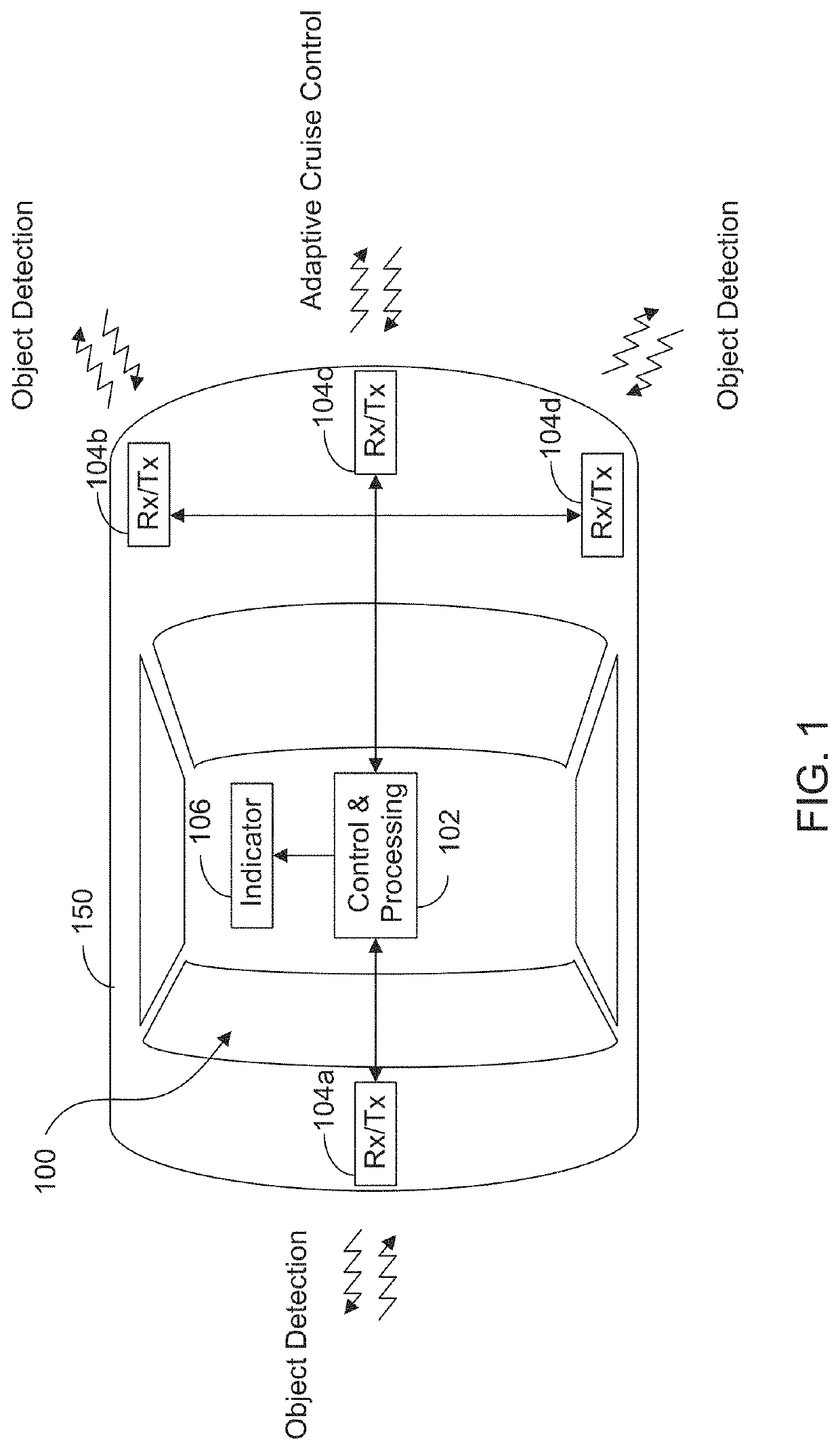
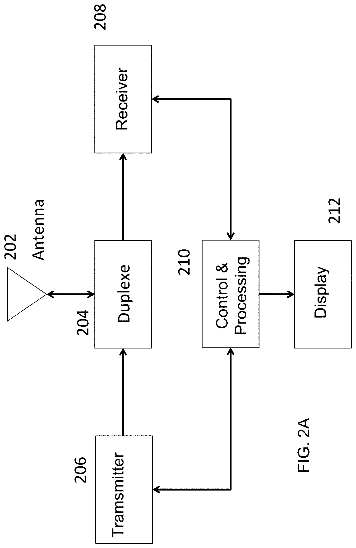
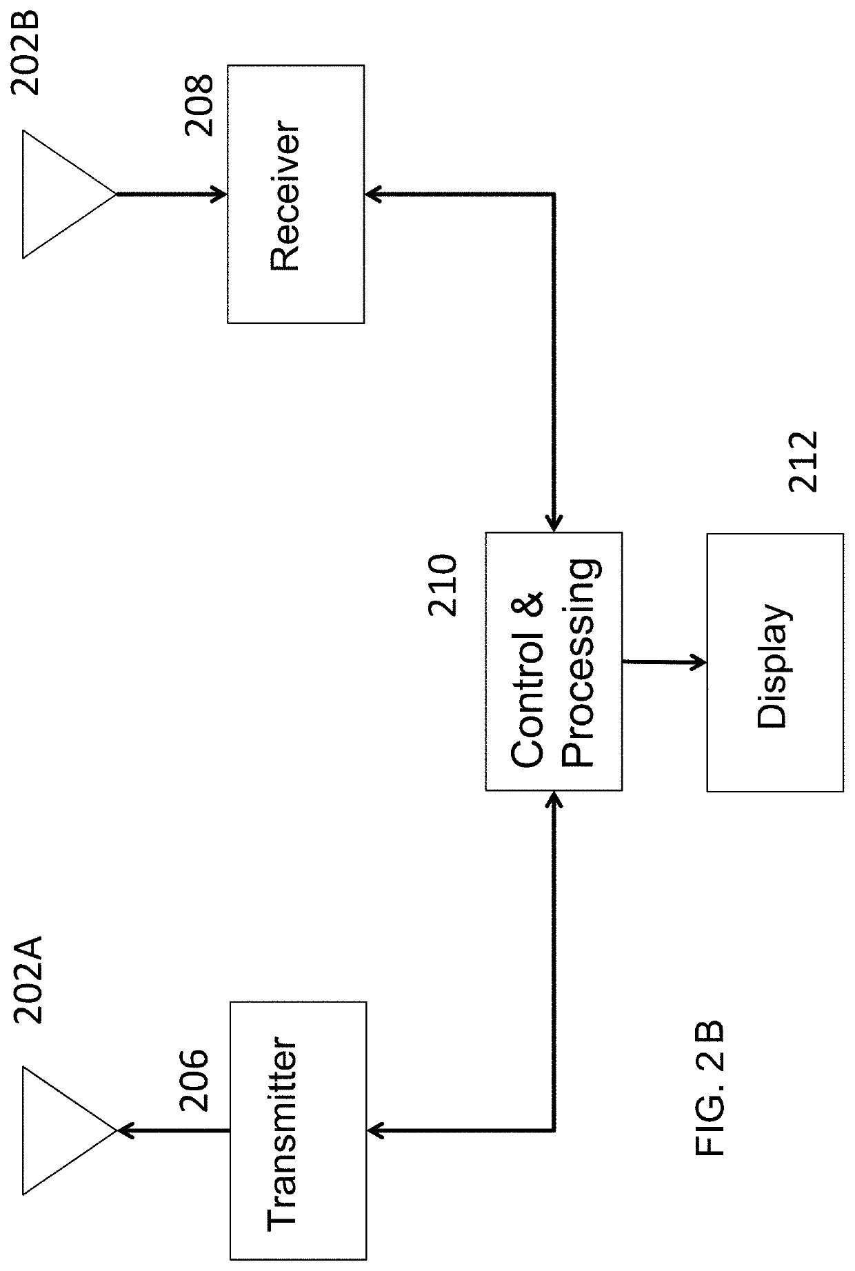
[0021]The present invention will now be described with reference to the accompanying figures, wherein numbered elements in the following written description correspond to like-numbered elements in the figures. Methods and systems of the present invention may achieve higher throughput of an exemplary radar system and have reduced memory requirements. Radar data cubes store complex numbers generated by processing the correlation between delayed versions of the transmitted signals with received signals. As discussed herein, the radar data cubes, which may be quite large, may be sparsified before storing to an external (e.g., off-chip) memory. The exemplary sparsification is achieved through one or more methods that include identification of regions in the computed radar data cubes of low absolute velocity and thresholding of remaining regions based on software thresholds or thresholds of noise floors estimated with power histograms. Exemplary embodiments may also achieve high throughpu...


PUM


Abstract

A radar includes transmitters, receivers, a memory, and a processor. The transmitters transmit radio signals, and the receivers receive reflected radio signals. The processor produces samples by correlating reflected radio signals with time-delayed replicas of transmitted radio signals. The processor stores this information as a first data structure, with information related to signals reflected from objects as a function of time (one dimension of the data structure) at various distances (a second dimension of the data structure) for various receivers (a third dimension of the data structure). The first data structure is processed to compute velocity and angle estimates, which are stored in second and third data structures, respectively. One or more memory optimizations are used to increase performance. Before storing the second and third data structures in a memory, the second and third data structures are sparsified to only include the outputs in specific regions of interest.

Description

CROSS REFERENCE TO RELATED APPLICATIONS[0001]This application is a continuation of U.S. patent application Ser. No. 15 / 893,021, filed Feb. 9, 2018, now U.S. Pat. No. 10,866,306, which claims the filing benefits of U.S. provisional application, Ser. No. 62 / 457,394, filed Feb. 10, 2017, which are both hereby incorporated by reference herein in their entireties.FIELD OF THE INVENTION[0002]The present invention is directed to radar systems, and in particular to radar systems for vehicles.BACKGROUND OF THE INVENTION[0003]The use of radar to determine range, velocity, and angle (elevation or azimuth) of objects in an environment is important in a number of applications including automotive radar and gesture detection. Radar typically transmits a radio frequency (RF) signal and listens for the reflection of the radio signal from objects in the environment. A radar system estimates the location of objects, also called targets, in the environment by correlating delayed versions of the receiv...

Claims


Application Information

Patent Timeline
Patent Type & Authority Patents(United States)
IPC IPC(8): G01S7/295G01S7/35G01S13/58G06F3/06G01S13/42
CPCG01S7/295G01S7/352G01S13/426G01S13/58G06F3/0608G06F3/0659G06F3/0661G06F3/0673G01S7/032G01S7/354G01S7/4017G01S7/4021G01S13/325G01S13/34G01S13/42G01S13/87G01S13/878G01S13/931G01S2013/93271G01S2013/93272G01S2013/93274
Inventor MAHER, MONIERBORDES, JEAN PIERREDAVIS, CURTIS
Owner UHNDER INC
Learn More