
Imaging apparatus and driving method thereof

a technology of imaging apparatus and driving method, which is applied in the direction of instruments, patient positioning for diagnostics, applications, etc., can solve the problems of large, heavy, and expensive image diagnostic equipment of the conventional ct system, and increase the size and cost of the ct system,

Active Publication Date: 2022-10-04
SHIZUKUISHI MAKOTO
View PDF55 Cites 3 Cited by
  • Summary
  • Abstract
  • Description
  • Claims
  • Application Information

AI Technical Summary

Benefits of technology

[0005]The detector or the like rotates inside the gantry around the body axis direction at a speed of about 1 to 2 revolutions per second. In order to supply power or read out an output signal from a detector or the like, transmission and reception of a signal, or transmission or reception of power is performed by a mechanical contact means called a slip ring. For the electrical connection by the slip ring, it is necessary to keep the rotation speed low and to reduce the number of output signal lines from the detector. In order to reduce the number of signal lines, serialization of the parallel signal read through the slip ring is adopted. However, when a large amount of image data is serially transmitted, the transmission frequency rises, and then it becomes necessary to develop some custom semiconductor elements such as a high-speed line buffer element, for example. With increase in the transmission frequency, more power consumption and heat generation cannot be avoided. In recent years, the slice width is being widened so that the wide area can be exposed by one-time X-ray pulse irradiation. As a result, in addition to increasing the weight of the gantry, it also needs to increase the size of the X-ray generator. The light receiving area (or the number of slices) in the body axis direction is expanded, which increases the light receiving area of the detector used or the total number of pixels requiring further increases the speed and the capacity of data transmission and high-speed real-time recording. A data processing speed exceeding 1 gigabyte / second is required when the number of slices is 64, for example. In order to record a large amount of data in real time at high speed, it is necessary to use a plurality of hard disks such as RAID (Redundant Arrays of Independent Disks) in combination. In addition to the realization of such high-speed, large-volume data processing, transmission and recording, it is also a problem to be solved by at least one example embodiment of the inventive concepts to reduce the radiation exposure dose of the subject.
[0006]The electric power feeding to the X-ray source or the like may cause a problem. Increasing the slice width, the X-ray source increases in size and the amount of current supplied to the X-ray source drive circuit and a high-voltage generation circuit has tended to increase as an X-ray tube current increases. Therefore, the slip ring needs to flow a large amount of current by sliding the brush on the slip ring, which may cause heat generation and seizure on the contact surface. Therefore, maintenance such as surface polishing of the slip ring and brush electrode or regular replacement of these parts are required. For the CT system installation, new design specifications on the building, floor strength, air conditioning equipment and their dedicated power supply system may be reconsidered. The cost of introducing a CT system is not only the installation cost of the CT system itself, but also the cost required for the building including the air conditioning and power supply system, or regular maintenance cost of the temperature and humidity management around the system or the entire building throughout the year. In the case of use outdoor or at a remote location, a large-capacity and stable commercial power for the CT system should be provided, however it may be difficult for a private power generator or a battery to supply enough electric power to the CT system. Therefore, we may need to use sunlight or other natural energy fully or partially in addition to the significant reduction of the power consumption and the energy loss of the CT system. Problems in the CT system to be solved are the reduction of its size, weight, power consumption, and the periodic maintenance load as well as enabling the CT system to be used hybridlike for multiple purposes.
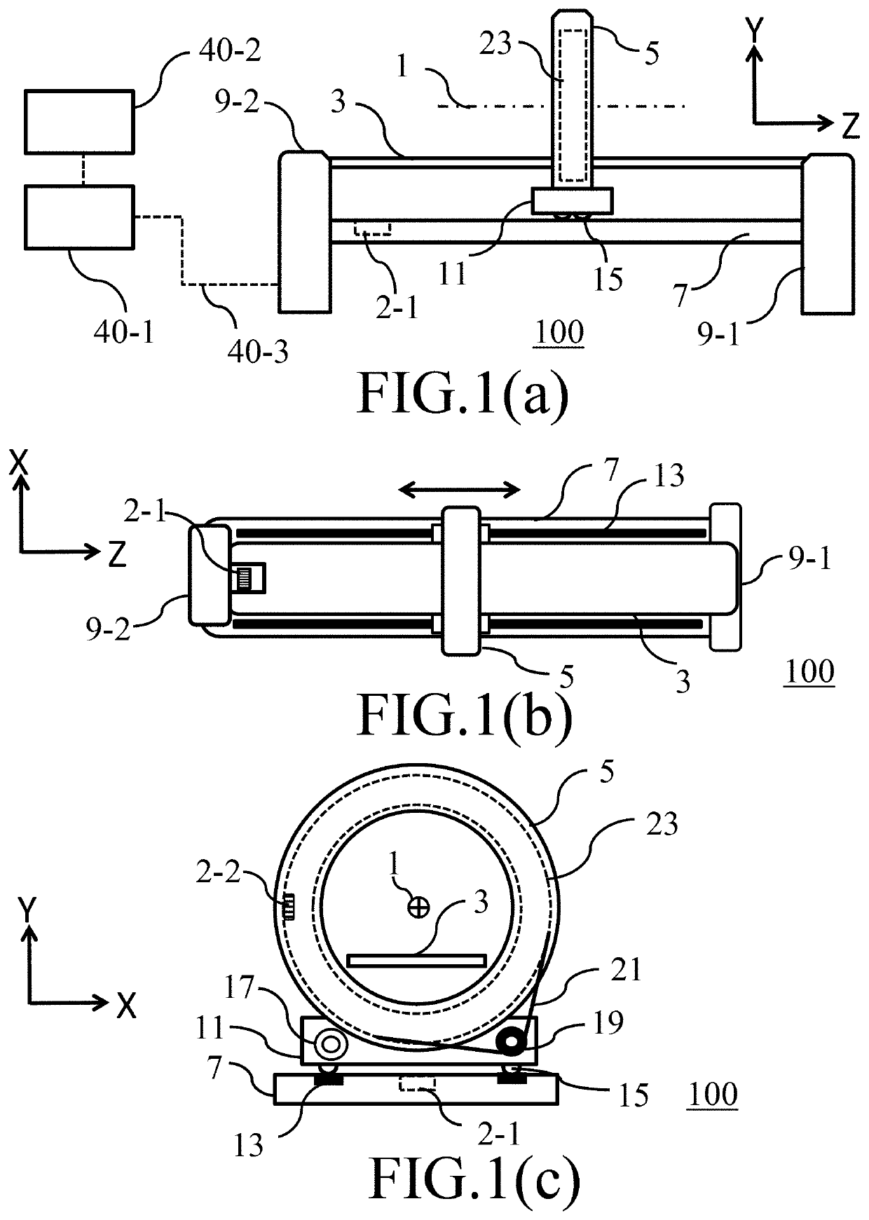
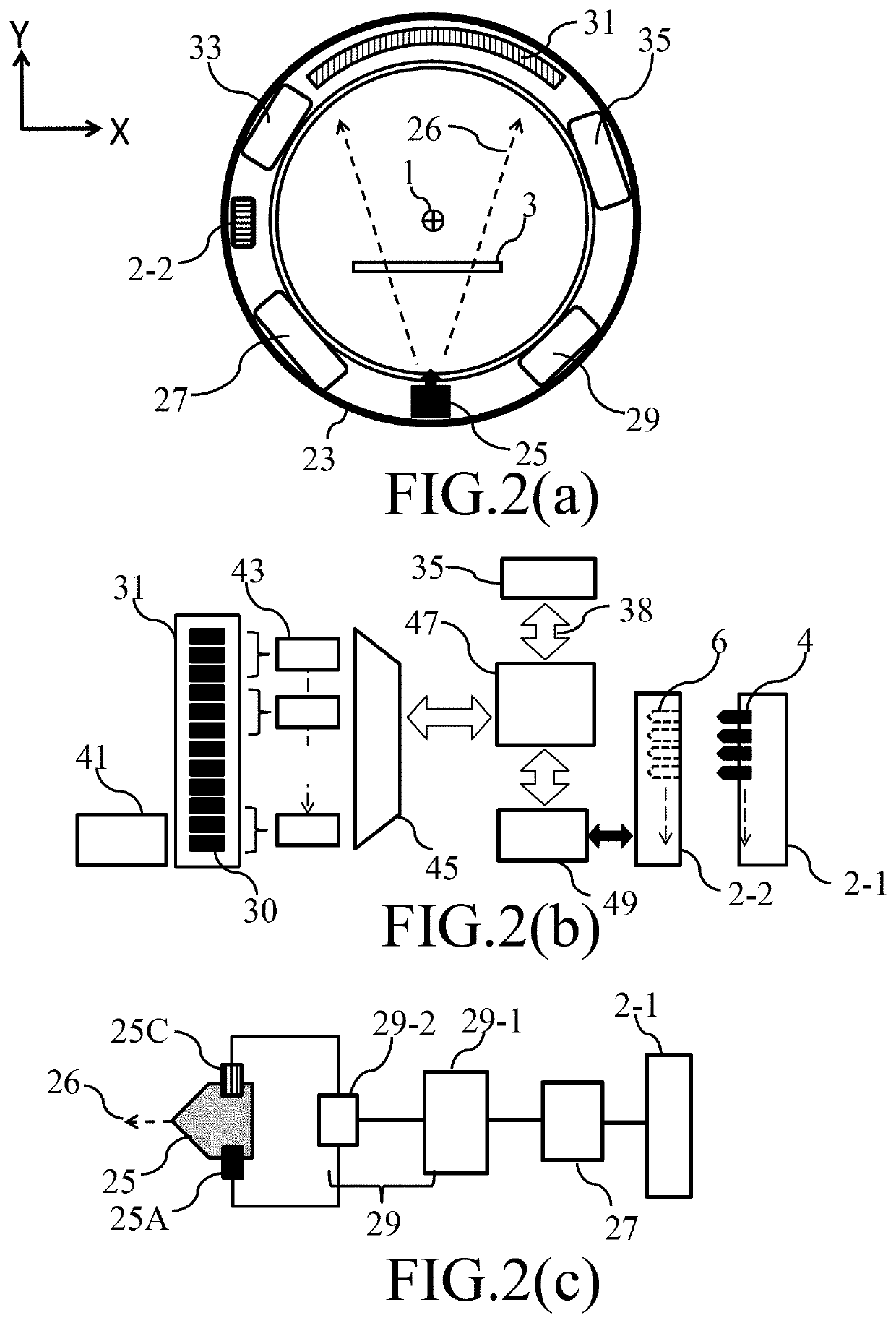
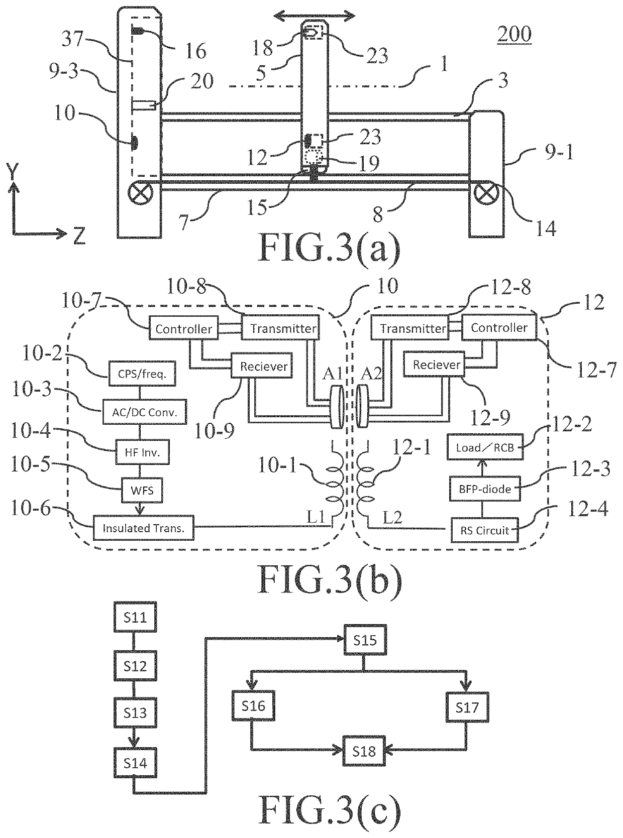
[0012]As is discussed in greater detail below, a CT system equipped with a detector array having low noise and low power consumption can be realized using a CMOS type sensor in which a signal processing circuit is integrated on-chip or by laminating an element on the sensor. In addition, since an extremely sensitive detector can be used to reduce the amount of the radiation exposure to the subject. Further, the reduction in the size and weight of the CT system and the reduction in power consumption can significantly reduce the space for installing the CT system, the construction of the building and the power supply, the air conditioning equipment, and the maintenance cost. Further, the slip ring and the brush electrode for making an electrical connection with the slip ring are not necessary, which greatly reduces sparks and breakdowns to improve the reliability. In addition, the annual maintenance cost for maintaining the optimal system performance such as periodical parts replacement and maintenance can be greatly reduced. Furthermore, the rotational moment of the rotating part after each imaging operation is converted into electric energy to be recovered, and the recovered electric energy can be reused for the rotational movement at the next imaging operation. As a result, it may reduce the size of the built-in rechargeable battery in the rotating part, shorten the charging time, or increase the number of times of photographing after charging. Moreover, since the components in the gantry, such as the X-ray source, the X-ray detector, and the rechargeable battery have a cartridge structure, the gantry itself does not need to be disassembled and repaired, and only the defective part is extracted, and a new part is installed instead. As a result, annual maintenance costs and equipment downtime to keep optimal performance of the CT system all the time may be greatly reduced. By replacing the gantry itself, the light source or the detector module according to the diagnostic purposes, it may not be necessary to install all kinds of image diagnostic apparatus like X-ray CT and PET (Positron Emission Tomography), for example, as for the orthopedic surgery, cardiology, and gastroenterology fields. According to at least one example embodiment of the inventive concepts, one hybrid CT system can be applied to various diagnoses in different medical fields. Even in an operating room or inpatient ward in a hospital, doctors can quickly and easily determine the initial diagnosis and treatment plan at the bedside without moving emergency or seriously injured patients who were carried in due to an accident. The CT system can be made smaller and lighter, and the power consumption or the load of repair and maintenance can be reduced. Therefore, the CT system can be moved by a vehicle and enables a quick and accurate initial diagnosis even in a remote place or in the area hit by a disaster, developing countries, other remote areas or depopulated areas by providing the latest and high-level medical services. As a result, the medical disparities due to natural disasters or regional conflicts, for example, can be eliminated.
[0033]According to at least one example embodiment, a method of driving the CT system may include causing the gantry to begin to move after rotational movement of the rotating part around the central axis has started, performing an imaging operation, the imaging operation including X-ray irradiation of the detector by the light source to cause the detector to generate digital data in response to the X-ray irradiation, recording digital data obtained from the detector in the image memory based on the X-ray irradiation, causing a counter electromotive force in the plurality of induction coils to be recovered by the energy recovery brake circuit as electric energy being caused by rotational kinetic energy of the rotating part, such that the rotational movement is decelerated while the energy recovery brake circuit charges a capacitor or the rechargeable battery with the electric energy, causing the gantry to stop at the predetermined position, and causing the digital data recorded in the image memory to be read from the rotating part interface through the host interface.

Problems solved by technology

A conventional CT system is a large, heavy, and expensive image diagnostic equipment.
In addition to the costs of the building where the CT system is installed including the cost of a large power supply and air conditioning systems, also maintenance cost to keep the CT system with optimal performance and conditions at all times cause a heavy financial burden.
Various unsolved technical problems, such as increased size and cost of a CT system, still remain and an effective breakthrough has not been found yet.
One of the factors that hinder the downsizing of conventional CT system may be the difficulty to reduce the size and weight of the gantry.
However, the X-ray source, the X-ray source drive control circuit, the air-cooling fan, for example, are heavy weight.
In addition, it is difficult to realize a small medical examination vehicle equipped with a CT system.
With increase in the transmission frequency, more power consumption and heat generation cannot be avoided.
As a result, in addition to increasing the weight of the gantry, it also needs to increase the size of the X-ray generator.
In addition to the realization of such high-speed, large-volume data processing, transmission and recording, it is also a problem to be solved by at least one example embodiment of the inventive concepts to reduce the radiation exposure dose of the subject.
The electric power feeding to the X-ray source or the like may cause a problem.
Therefore, the slip ring needs to flow a large amount of current by sliding the brush on the slip ring, which may cause heat generation and seizure on the contact surface.
The cost of introducing a CT system is not only the installation cost of the CT system itself, but also the cost required for the building including the air conditioning and power supply system, or regular maintenance cost of the temperature and humidity management around the system or the entire building throughout the year.
In the case of use outdoor or at a remote location, a large-capacity and stable commercial power for the CT system should be provided, however it may be difficult for a private power generator or a battery to supply enough electric power to the CT system.
Problems in the CT system to be solved are the reduction of its size, weight, power consumption, and the periodic maintenance load as well as enabling the CT system to be used hybridlike for multiple purposes.
As a result, it may reduce the size of the built-in rechargeable battery in the rotating part, shorten the charging time, or increase the number of times of photographing after charging.

Method used


Image

  • Imaging apparatus and driving method thereof
  • Imaging apparatus and driving method thereof
  • Imaging apparatus and driving method thereof

Examples


Embodiment Construction

[0064]Detailed example embodiments are disclosed herein. However, specific structural and functional details disclosed herein are merely representative for purposes of describing example embodiments. Example embodiments may, however, be embodied in many alternate forms and should not be construed as limited to only the embodiments set forth herein.

[0065]Accordingly, while example embodiments are capable of various modifications and alternative forms, example embodiments of the inventive concepts are shown by way of example in the drawings and will herein be described in detail. It should be understood, however, that there is no intent to limit example embodiments to the particular forms disclosed, but to the contrary, example embodiments are to cover all modifications, equivalents, and alternatives falling within the scope of example embodiments. Like numbers refer to like elements throughout the description of the figures.

[0066]It will be understood that, although the terms first, ...


PUM


Abstract

A computed tomographic (CT) system includes a gantry having a rotating part including a light source, a light source drive control circuit, a rechargeable battery, and a rotating part interface. The gantry includes a detector, a detector control and signal processing circuit, and an image memory. The rotating part may rotate around a central axis. The CT system includes a gantry table on which the gantry is mounted and which includes a host interface. The CT system includes a motor that may cause the gantry to move within a gantry moving range, and a control unit that may process and display image data obtained from the gantry. The rotating part interface may face the host interface, such that the rotating part and host interfaces are configured to be electrically connected with each other, based on the gantry being at a predetermined position within the gantry moving range.

Description

CROSS-REFERENCE TO RELATED APPLICATIONS[0001]This application is a Continuation of PCT / JP2019 / 050276 filed on Dec. 23, 2019, which claims priority to Japanese Patent Application No. 2018-242594 filed on Dec. 26, 2018, in the Japanese Patent Office (JPO), and Japanese Patent Application No. 2019-165058 filed on Sep. 11, 2019, in the JPO, the entire contents of each of which are incorporated herein by reference.BACKGROUND1. Technical Field[0002]Example embodiments relate to an imaging apparatus such as a computer tomographic (CT) system and a driving method thereof enabling high spatial, timing and energy resolution with smaller form factor and lower power consumption.2. Related Art[0003]An imaging apparatus, for example, an X-ray computed tomographic (CT) system comprises a gantry including a rotating part that rotates around an imaging target, a bed on which a subject is placed so as to pass through the inside of the gantry in the direction of the central axis of the rotation, a mov...

Claims


Application Information

Patent Timeline
Patent Type & Authority Patents(United States)
IPC IPC(8): A61B6/00A61B6/03A61B6/04G16H40/67
CPCA61B6/4435A61B6/032A61B6/0407A61B6/4241A61B6/461G16H40/67A61B2562/046G16H30/20G16H40/63A61B6/56A61B6/4014
Inventor SHIZUKUISHI, MAKOTO
Owner SHIZUKUISHI MAKOTO
Learn More