Hip implant device

a technology of implants and proximal joints, applied in the field of implants, can solve the problems of increased wear and tear of metal-to-metal joints, inability to drill from two sides, and inability to guarantee the alignment of two drill holes, and achieve the effect of strengthening the binding of the plastic joint surfa

Active Publication Date: 2022-11-15
OMNES MEDICAL INC
View PDF5 Cites 0 Cited by
  • Summary
  • Abstract
  • Description
  • Claims
  • Application Information

AI Technical Summary

Benefits of technology

[0009]In an alternative embodiment, the metal femoral head base can have stabilization features that enhance binding of the plastic joint surface of the femoral head onto that base for a secure femoral head construction. For example, the femoral head base may have dimples and peripheral mounds over its surface to create a stable interface with the polymer head.

Problems solved by technology

However, this combination generated metallic particles during use to the detriment of the implant recipient's health, and therefore such metal-to-metal joints are no longer permitted.
Replacing the metallic acetabular cup with one made of thick bio-compatible polymer material resulted in considerably more wear during use.
Over time, the relatively smaller femoral head wore down the cup surface until it no longer fit properly within the cup, resulting in dislocations.
A further complication of implant devices of this type are that a three-piece construction is surgically implanted most easily when drilling for the lag screw portion is done from two sides, both through the femoral neck and also through the side of the femoral shaft (where the relatively shorter distance to the long nail portion can help ensure that the lag screw hole in the long nail portion is in the proper position in the femoral shaft for accepting the lag screw portion coming from the femoral neck).
However, drilling from two sides does not guarantee that the two drill holes will align.
Furthermore, with existing standard implants, the femoral neck angle of hip implant is fixed; thus, it could cause misalignment if it differs significantly from the original femoral neck angle.
The current hip resurfacing implant includes metal to metal contact, and any contact debris can cause serious health problems.
However, the resurfacing hip implant is susceptible to these three types of fracture; whereas the mini hip implant is only susceptible to the intertrochanteric fracture.
The mini implant, however, is susceptible to the intertrochanteric fracture; so, it requires strong fusion between the cancellous and implant surfaces.
Still further, the standard hip implant can cause a subtrochanter fracture during or after the surgery, which occurs along the femoral stem just below the root of the femoral neck.
Additionally, the resection position for the standard implant can result in malposition of the artificial femoral head center due to a loss of anatomical center position.

Method used


Image

  • Hip implant device
  • Hip implant device
  • Hip implant device

Examples


Embodiment Construction

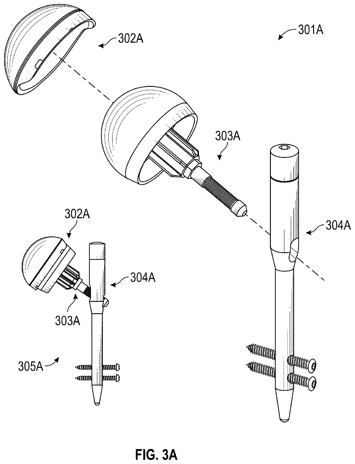
[0042]FIG. 3A shows the assembled view 305A and exploded view 301A of an embodiment of the current invention. The implant consists of the three portions: an acetabular cup 302A, a femoral head and neck 303A and a main body shaft 304A.

[0043]The design for this implant uses only bio-compatible materials, such as polyethylene, polyether ether ketone (PEEK) or ultra-high-molecular-weight polyethylene (UHMWPE), and bio-compatible metal, such as cobalt, chromium, titanium, alloys thereof, or medical-grade stainless steel 316.

[0044]FIG. 3B shows a coronal view 301B of the resurfacing hip implant of the invention 302B, which shows the anatomically positioning in the proximal femur 303B. The acetabulum implant cup 304B is inserted into the hip's acetabulum anatomy 305B. The femoral head and neck 306B and the main body shaft 307B are inserted into the proximal femur 303B. Bone screws 308B secure the main body shaft 307B at the femoral shaft region through the cortical bone 309B from lateral t...


PUM


Abstract

A hip implant is provided that includes a metal acetabular cup to be inserted into an acetabulum of the pelvis, a femoral head and neck portion with a polymer femoral head molded onto a metal formal head base that is attached to a metal femoral neck rod configured to be inserted into the neck of a femur, and a metal main body shaft configured to be inserted into a femoral shaft region of the femur and secured by bone screws. The head base may have stabilizing features, such as dimples and peripheral mounds, over which the femoral head is molded. The main body shaft also has diagonal hole located at the center line of the neck of the femur to receive the femoral neck rod at an adjustable angle. The femoral head interfaces with the acetabular cup as a smooth plastic-to-metal spherical-surface joint.

Description

TECHNICAL FIELD[0001]The present invention relates to hip implants for the acetabular-femoral joint.BACKGROUND ART[0002]U.S. Pat. No. 8,840,675 to Song describes a “minimal invasive” hip arthroplasty device comprising a long nail portion, a lag screw portion, and a resurfacing head interfacing with an acetabular cup. The long nail portion is inserted into the shaft of the femur. Distal locking screws fix the long nail portion to the femur. The lag screw portion inserts into the neck of the femur and into a lag screw hole of the long nail portion. A set screw within the hollow long nail portion engages with locking grooves on the lag screw portion. The resurfacing head screws into a hole in the neck end of the lag screw portion.[0003]In implant devices of this type, both the acetabular cup and resurfacing head were, at one time, both made of bio-compatible metals for a metal-to-metal joint. However, this combination generated metallic particles during use to the detriment of the impl...

Claims


Application Information

Patent Timeline
Patent Type & Authority Patents(United States)
IPC IPC(8): A61F2/34A61F2/36A61F2/30
CPCA61F2/34A61F2/3609A61F2/3094A61F2/30767A61F2/3601A61F2002/3652A61F2220/0033A61F2310/00023A61F2310/00029A61F2310/00059A61F2002/3446A61F2/3603A61F2/3662A61F2002/368A61F2002/30507A61F2002/30383A61F2002/304A61F2002/30405A61F2002/30538A61F2002/30971A61F2002/30004A61F2002/30884A61F2002/349A61F2002/30616A61B17/744A61B17/748
Inventor SONG, BENJAMIN SOOIL
Owner OMNES MEDICAL INC
Why Eureka
Try Eureka