Apparatus and method for active reduction of the noise emission from jet engines and for jet engine diagnosis

a technology of active reduction and noise emission, applied in the direction of propulsive elements, air transportation, cosmonautic components, etc., can solve the problems of increasing weight, reducing the efficiency of aircraft, and reducing the effect of noise reduction

Inactive Publication Date: 2001-09-27
NAGEL FRIEDMUND
View PDF0 Cites 21 Cited by
  • Summary
  • Abstract
  • Description
  • Claims
  • Application Information

AI Technical Summary

Problems solved by technology

The measures described for soundproofing, silencing, structure-borne sound decoupling, etc., generally lead to increased weight.
In general, all the noise protection measures which increase weight reduce the efficiency of aircraft by reducing the payload and increasing the fuel consumption.
Furthermore, effective noise reduction is linked to high development costs for locating and combating the individual noise sources and the noise transmission paths.
In the end, this cost is incurred for all new internal equipment in a jet aircraft.
Another general disadvantage of the systems mentioned above is that they do not result in any reduction in the noise emission in the a

Method used


Image

  • Apparatus and method for active reduction of the noise emission from jet engines and for jet engine diagnosis
  • Apparatus and method for active reduction of the noise emission from jet engines and for jet engine diagnosis
  • Apparatus and method for active reduction of the noise emission from jet engines and for jet engine diagnosis

Examples


Embodiment Construction

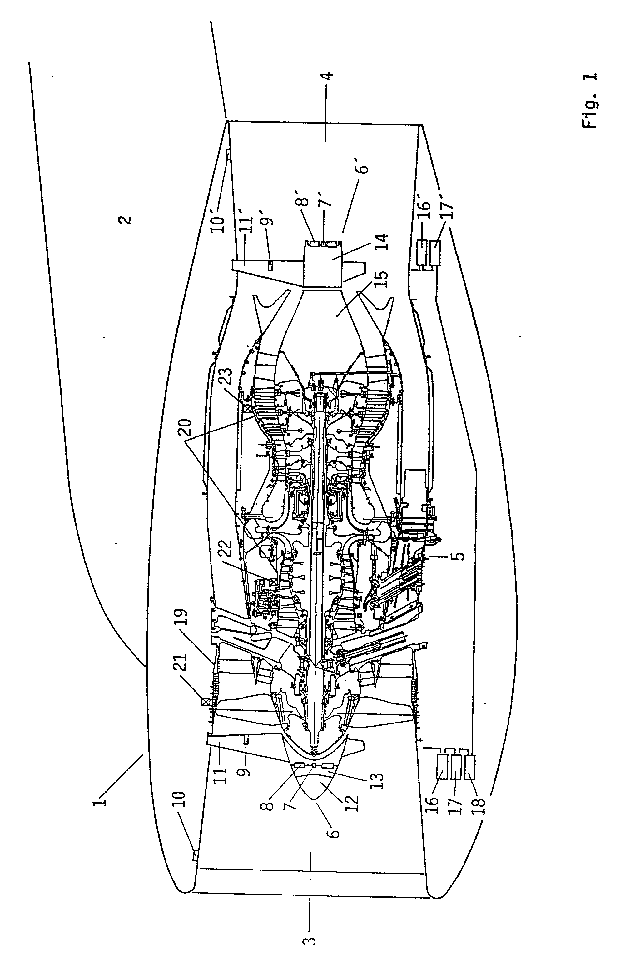
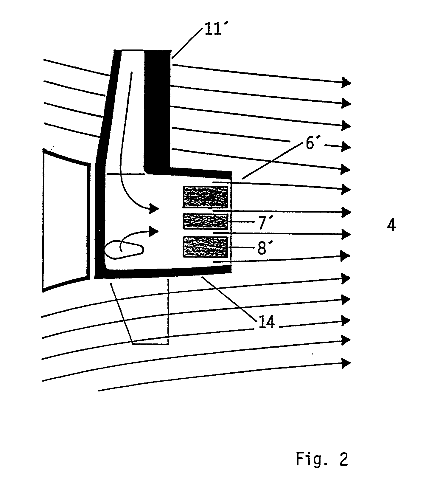
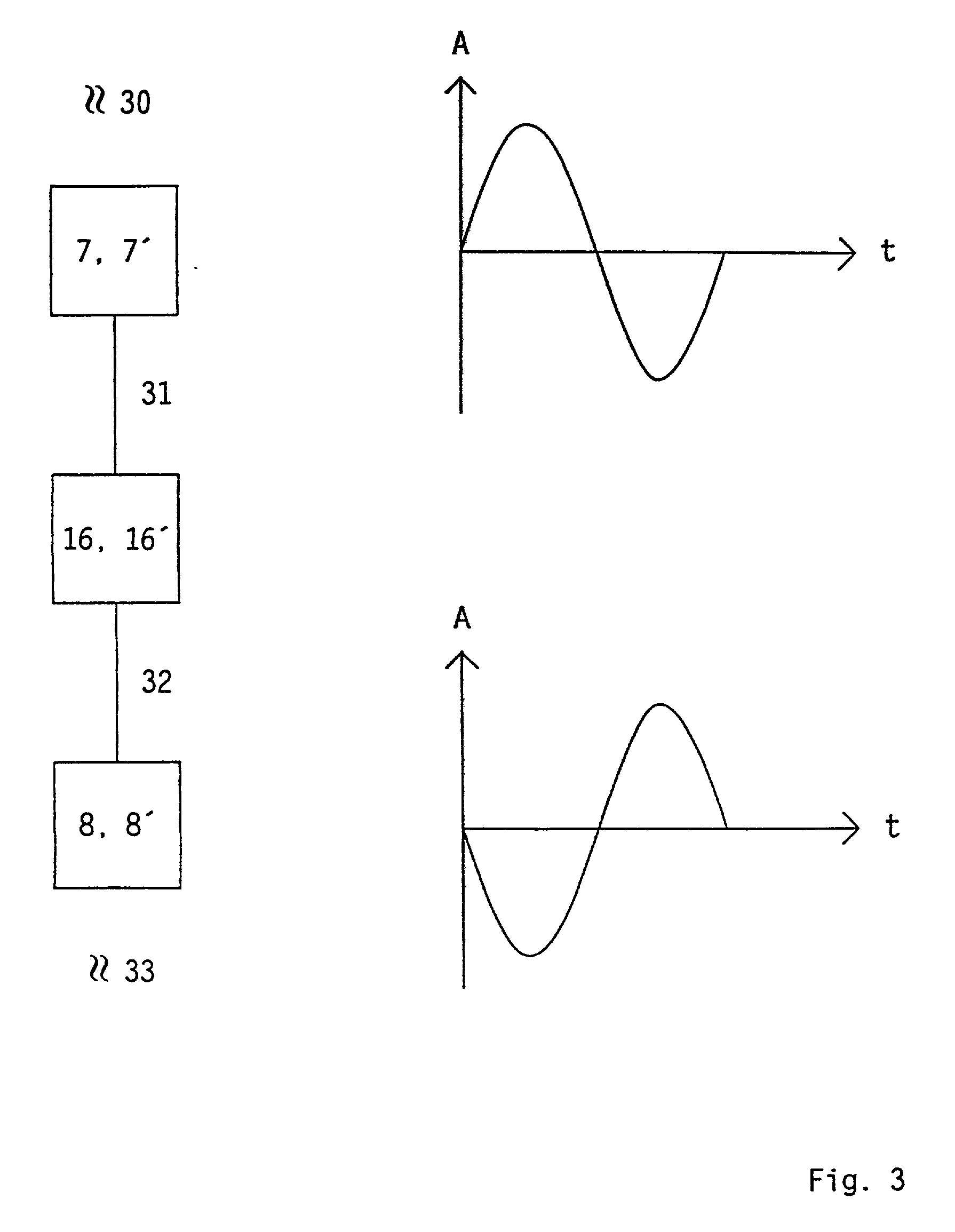
[0076] FIG. 1 shows a jet engine 1, in this case a twin-spool bypass engine, which is arranged on a suspension device 2. The jet engine 1 is equipped with an apparatus to reduce noise emission. The jet engine 1 has a front air inlet 3 and a rear gas outlet 4. The actual engine 5 is fitted between the front air inlet 3 and the rear gas outlet 4. The jet engine 1 shown in FIG. 1 has both in the air inlet 3 as well as in the gas outlet 4, a first acoustic transducer 7 and / or 7'. The first acoustic transducer 7 may be a microphone, and a second acoustic transducer 8 and / or 8' may be a loudspeaker. The front noise compensation unit 6 is monitored by an electronic control unit 16, and the rear compensation unit 6' is monitored by an electronic control unit 16'.

[0077] The front noise compensation unit 6 comprises the acoustic transducers 7, 8, and is fitted in a cone 12 in the air inlet 3. The cone has an opening 13 for the acoustic transducers 7, 8 to communicate acoustically with the com...


PUM


Abstract

An apparatus and a method for active reduction of the noise emission from a jet engine having an air inlet, a gas outlet and an engine arranged between the air inlet and the gas outlet. A first acoustic transducer is arranged in the air inlet upstream of the engine and/or in the gas outlet downstream of the engine in order to convert sound waves into first signals that are a measure of the frequency, amplitude and phase of the sound waves. An electronic control unit converts the first signals into second signals. A second acoustic transducer is centrally arranged in the air inlet upstream of the engine and/or in the gas outlet downstream of the engine in order to convert the second signals into compensation sound waves whose frequency, amplitude and phase are such that the sound waves and the compensation sound waves at least partially cancel one another out.

Description

[0001] The present invention relates to an apparatus and a method for active reduction of the noise emission from jet engines and for their diagnosis.DESCRIPTION OF THE RELATED ART[0002] The internal noise, as well as the external noise, from jet aircraft are nowadays governed primarily by the noise emissions from their jet engines. As air traffic increases, both the reduction of the internal noise in aircraft and, in particular, the reduction of the aircraft noise to which those living close to airfields are subjected are becoming more important.[0003] Attempts are frequently made to achieve a reduction in the noise level in the interior of aircraft by further improving passive sound-proofing and silencing. The efforts to reduce noise also include measures relating to the decoupling of structure-born sound. In this case, the aim is to prevent the sound emitted from a jet engine being transmitted to other parts of the aircraft, particularly to parts which are connected to the interi...

Claims


Application Information

Patent Timeline
IPC IPC(8): F02C7/045F02C7/24F02K1/82
CPCF02C7/045F02K1/827F05D2260/962Y02T50/671Y02T50/60
Inventor NAGEL, FRIEDMUND
Owner NAGEL FRIEDMUND
Why Eureka
Try Eureka