
Line-type film-forming method and reflector formed thereby

a film-forming method and film-forming technology, applied in signalling/lighting devices, chemical vapor deposition coatings, vehicle headlamps, etc., can solve the problems of complex construction, poor quality of many base materials, and formation of aluminum metallized films and plasma polymerized films

Inactive Publication Date: 2001-10-04
KOITO MFG CO LTD
View PDF0 Cites 2 Cited by
  • Summary
  • Abstract
  • Description
  • Claims
  • Application Information

AI Technical Summary

Benefits of technology

[0073] The effect achievable by the line-type film-forming method is as follows:[0074] The productivity is improved because the work required to follow the step of setting the synthetic-resin base materials can be simplified, and the lead time can also be shortened. Moreover, the steps of forming metallized aluminum, and plasma polymerized, films that have heretofore been separately followed can now be performed in series, whereby the work of conveying synthetic-resin base materials from the aluminum metallizing stage to the plasma polymerized film forming stage is unnecessary, which results in improving workability.[0075] According to the present invention, films are formed while the case is laterally passed through an aluminum metallizing chamber and a plasma polymerized film forming chamber. Therefore, a complicated mechanism for rotating base materials in any metallized-film forming unit can be dispensed with, so that the maintenance and handling of the metallizing-film forming unit is made easy as well as with reduced manufacturing cost.[0076] The case for housing the synthetic-resin base materials is re-cycled to the side of the aluminum metallizing chamber whereby it can be used repeatedly, so that the efficiency of workability is improved.[0077] The pluralities of aluminum metallizing and plasma sources respectively are arranged in the lower regions of the aluminum metallizing and the plasma polymerized film forming chambers. With respect to aluminum, a metallized film is formed on both the front surface and back surface of each reflector base material by moving the aluminum around toward the back surface of the base material. In contrast, the silicone is restricted in its diffusing area, so that the silicone polymerized film is formed only on the front surface (the face directed downward) of each reflector base material. Because the aluminum metallized film has been formed on the back surface of the reflector thus obtained, it is ensured that an electromagnetic shielding function can be achieved. That is, since the aluminum metallized film is exposed to the back surface of the reflector, without being covered by a protective film, the back surface of the reflector can be grounded. Therefore, reflectors fit for use in automotive discharge headlamps can be provided.[0078] The present invention is not limited to the specific above-described embodiment. It is contemplated that numerous modifications maybe made to the line-type film-forming method, and reflector formed thereby, of the present invention without departing from the spirit and scope of the invention as defined in the following claims.

Problems solved by technology

However, such a method still presents the following technical problem, namely, that aluminum metallized films and plasma polymerized films are formed on both sides of synthetic-resin base materials.
Moreover, as the rotating and revolving system is equipped with a rotating mechanism, as an aluminum metallizing system, it is complicated in construction.
However, the drawback of the antenna-type system is that: it is a batch production system wherein a large number of predetermined base materials are disposed in a chamber and, after a predetermined time (about 40 minutes) for forming metallized films and plasma polymerized films elapses, all of the base materials are taken out of the chamber; a lead time, necessary for disposing the base materials in the chamber is long; and when any poor quality is found in the relevant lot, many of the base materials will also be found poor in quality.
An additional problem is that the formation of plasma polymerized films by the antenna-type system results in low plasma density in general, and causes not only slow film formation but also uneven film distribution.
The problem in this case is, technically, that when a plasma polymerized film (silicone polymerized film) is also formed on the aluminum metallized film on the back surface of the reflector, as in the antenna-type system, the aluminum metallized film may not be grounded.

Method used


Image

  • Line-type film-forming method and reflector formed thereby
  • Line-type film-forming method and reflector formed thereby
  • Line-type film-forming method and reflector formed thereby

Examples


Embodiment Construction

[0042] A preferred embodiment of the present invention will now be described with reference to the accompanying drawings.

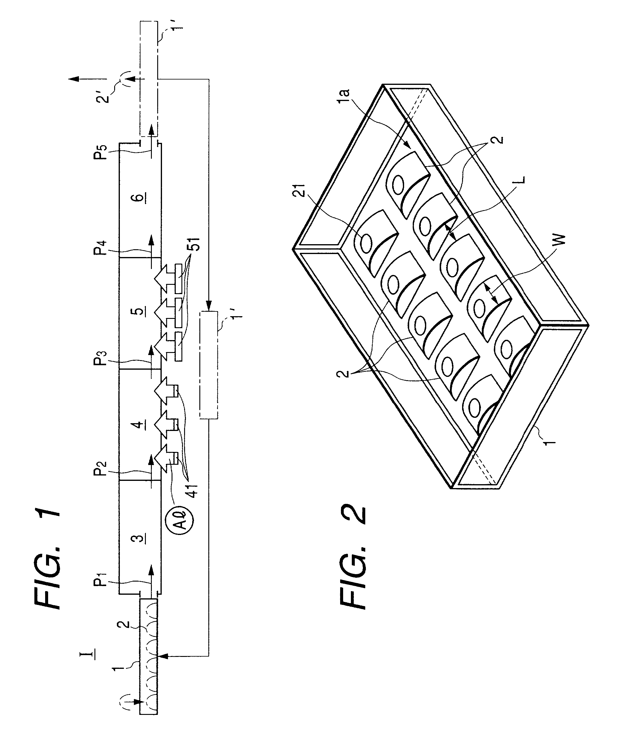
[0043] First, FIG. 1 is a simplified diagram illustrating the steps of forming films in a line-type method embodying the invention, wherein an aluminum metallized film and a plasma polymerized film are formed on each of the synthetic-resin base materials forming a reflector to be mounted in a vehicular lamp.

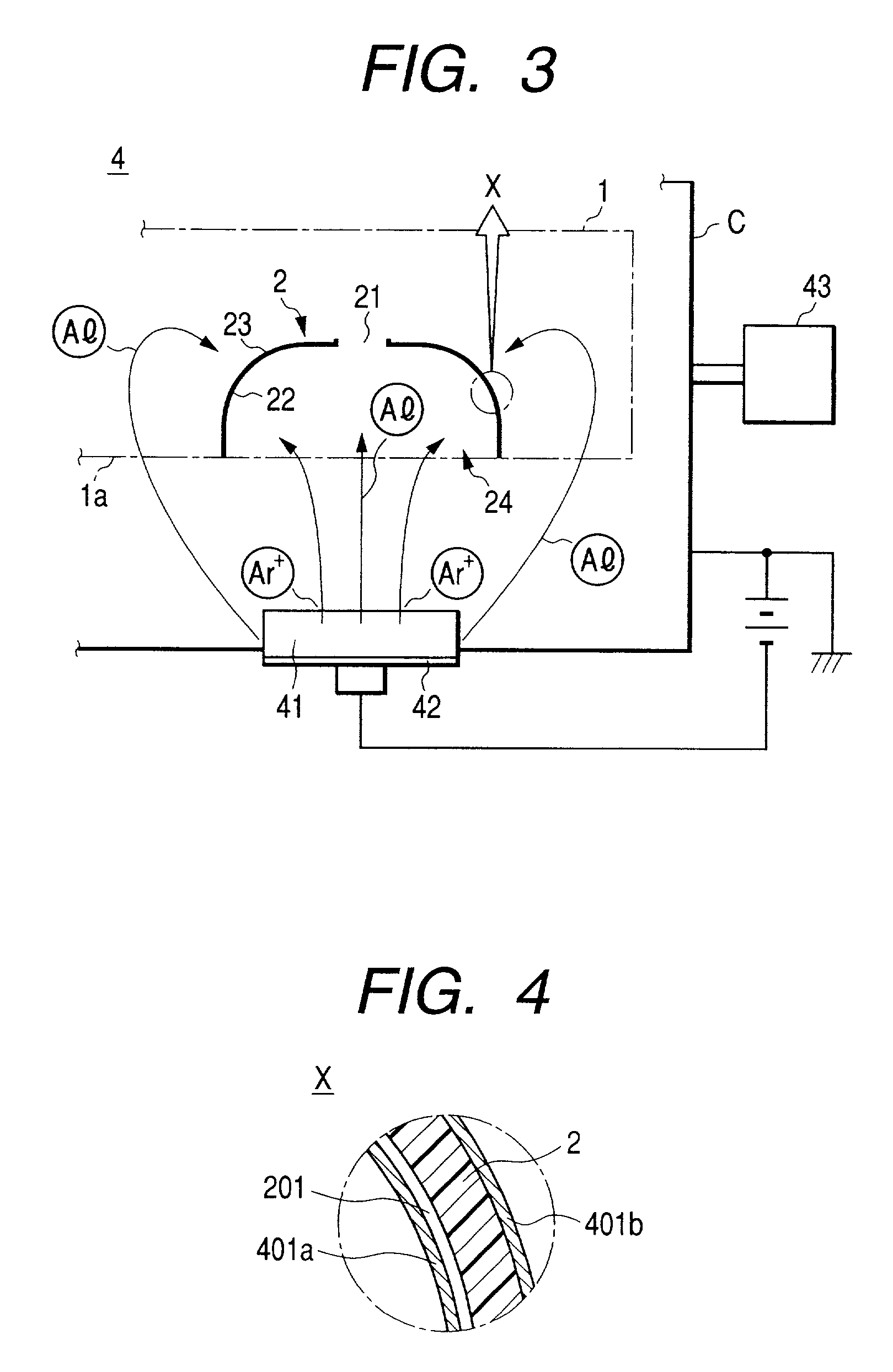
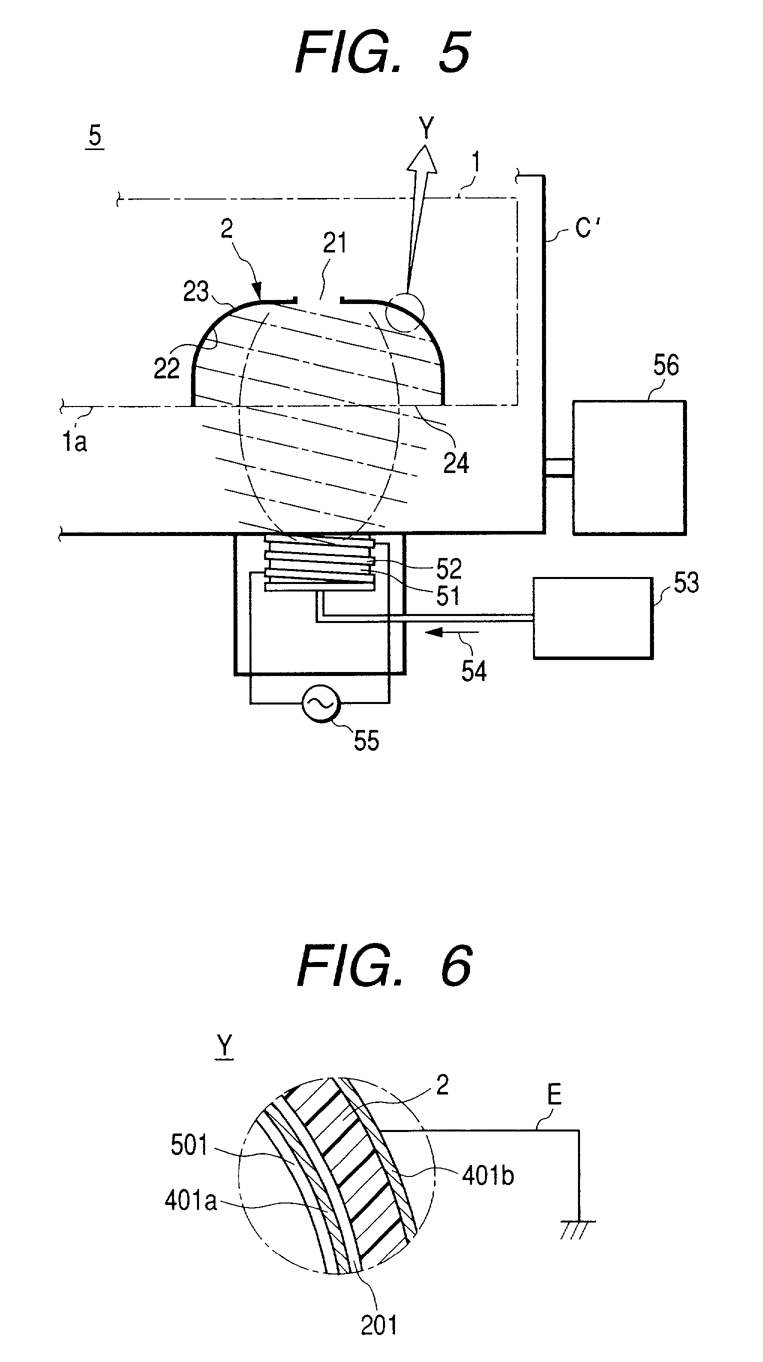
[0044] With reference to FIG. 1, the steps of forming the films, according to the line-type method of the present invention, will be described. At a pretreatment step (not shown), a reflector base material 2 is formed with an undercoat layer 201 (see FIGS. 4 and 6) for securing the smoothness of the base material surface. The reflector base material 2 then is conveyed to a position I where film forming work is started.

[0045] While holding the back surface side (rear top portion side) of each reflector base material 2 with the hand, a worker manages not to touch...


PUM


Abstract

A line-type film-forming method for sequentially forming aluminum metallized films and silicone plasma polymerized protective films on a plurality of synthetic-resin base materials. The films are formed by moving a case, which houses the synthetic-resin base materials, successively in line through an aluminum metallizing chamber and a plasma polymerized film forming chamber so as to form a reflector that can be mounted in a discharge headlamp.

Description

[0001] 1. Field of the Invention[0002] The present invention relates to a method of forming aluminum metallized films and protective films--such as silicone plasma polymerized films for protecting the aluminum metallized films--on synthetic-resin base materials through lined up processing stages.[0003] More specifically, the invention relates to a method of forming aluminum metallized films and silicone protective films through the steps of housing and lining up, in a predetermined case, a plurality of synthetic-resin base materials for use in various reflectors--such as reflective mirrors for use in vehicular lamps such as automobiles, two-wheeled automobiles and the like, particularly synthetic-resin base materials of reflectors to be mounted in discharge headlamps--and passing the case successively through an aluminum metallizing chamber and a silicone protective film forming chamber. The invention also relates to a reflector formed by the above-described method.[0004] 2. Descrip...

Claims


Application Information

Patent Timeline
IPC IPC(8): F21S8/10C23C14/06C23C14/20C23C14/56F21V7/00F21V7/22F21V17/00F21Y101/00
CPCC23C14/205C23C14/56F21S48/1394Y10T428/12028G02B1/105G02B5/0866F21V7/22F21S41/37F21V7/24F21V7/28G02B1/111G02B1/14
Inventor INABA, TERUAKI
Owner KOITO MFG CO LTD
Learn More