Handheld type four-cycle engine

US20010029921A1Inactive Publication Date: 2001-10-18HONDA MOTOR CO LTD

Image

  • Handheld type four-cycle engine
  • Handheld type four-cycle engine
  • Handheld type four-cycle engine

Examples


Embodiment Construction

[0034] An embodiment of the present invention is explained below by reference to the attached drawings.

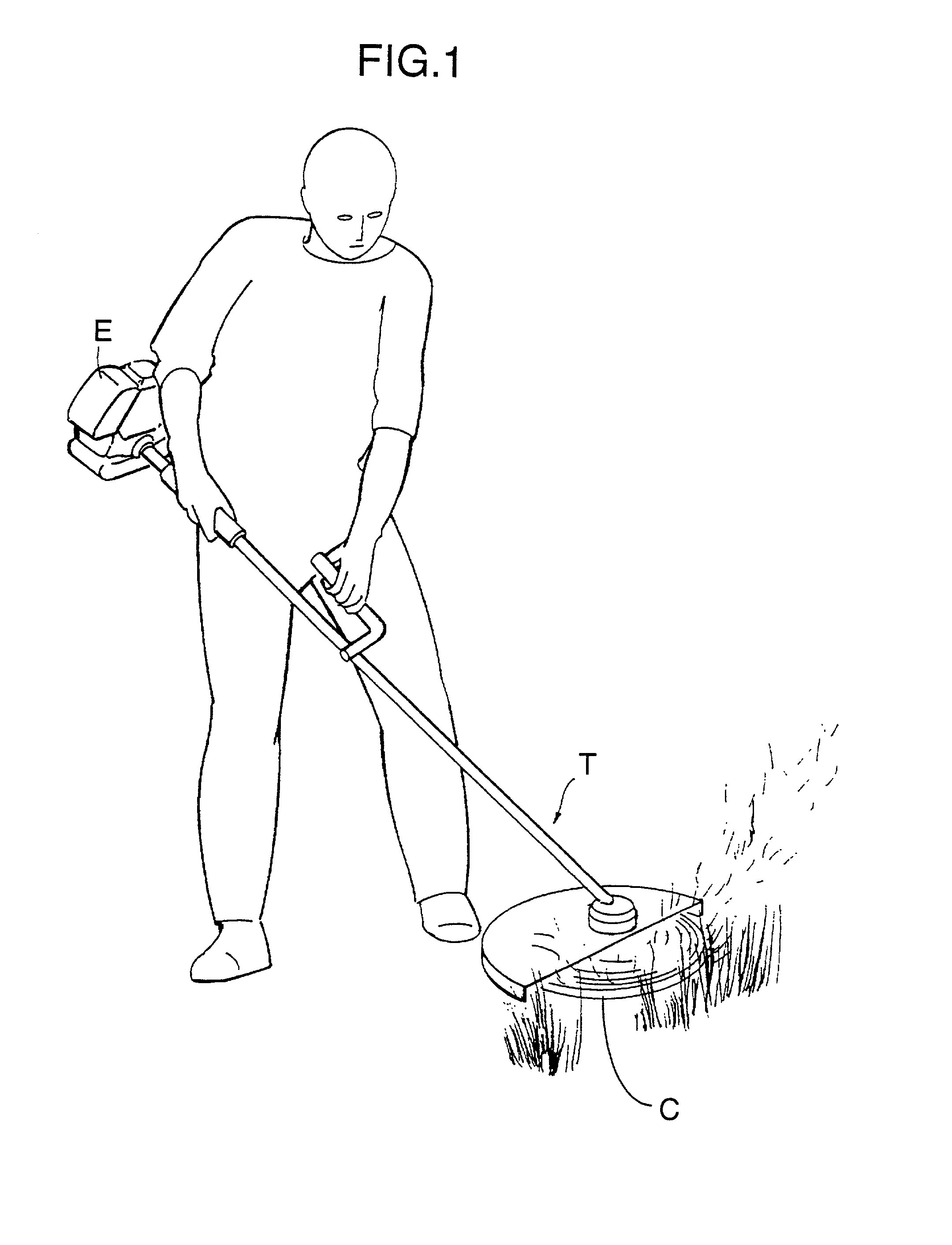
[0035] As shown in FIG. 1, a handheld type four-cycle engine E is attached as a source of power to the drive section of, for example, a powered trimmer T. Since the powered trimmer T is used in a manner in which a cutter C is positioned in various directions according to the operational conditions, the engine E is also tilted to a large extent or turned upside-down as a result and the operational position is unstable.

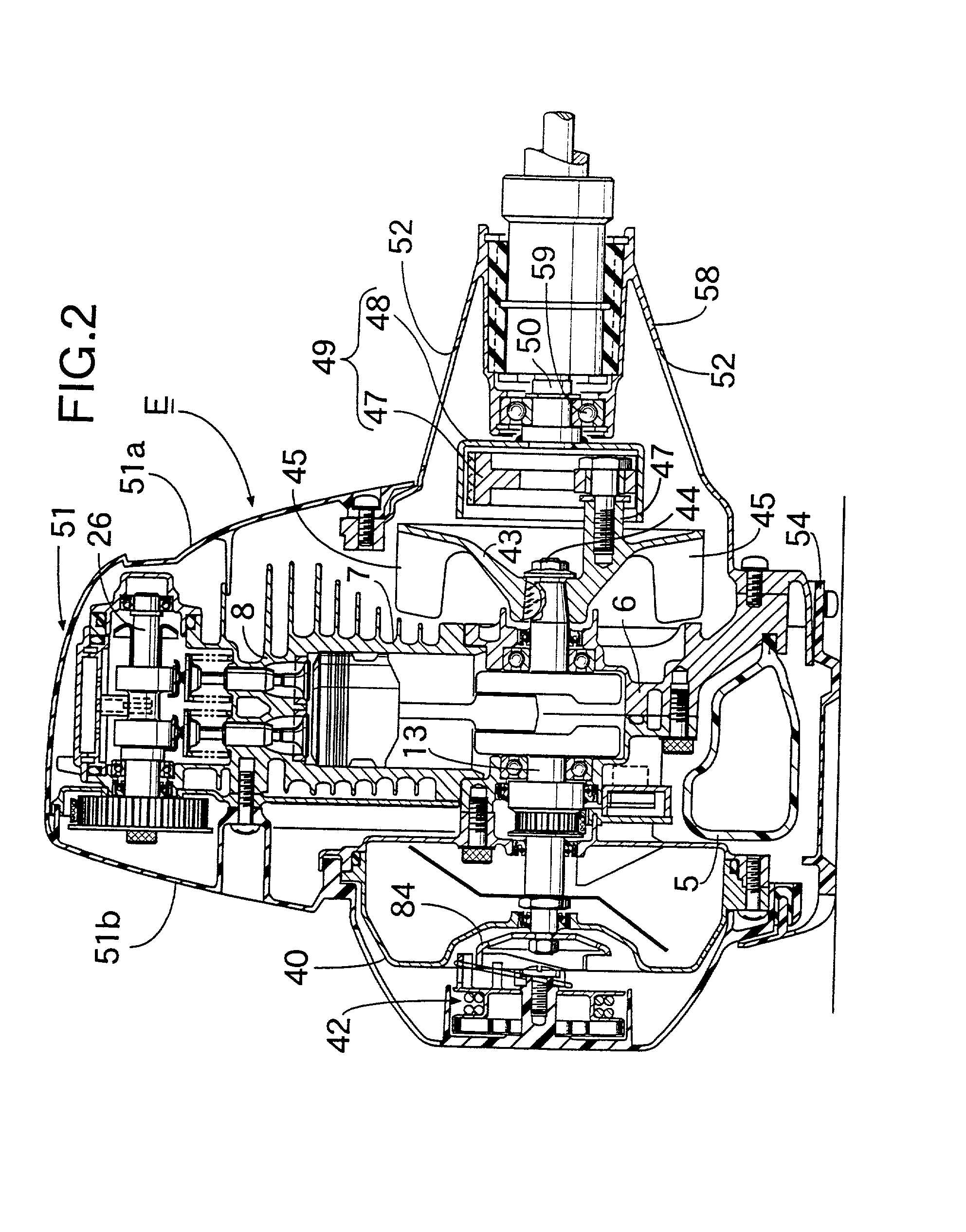
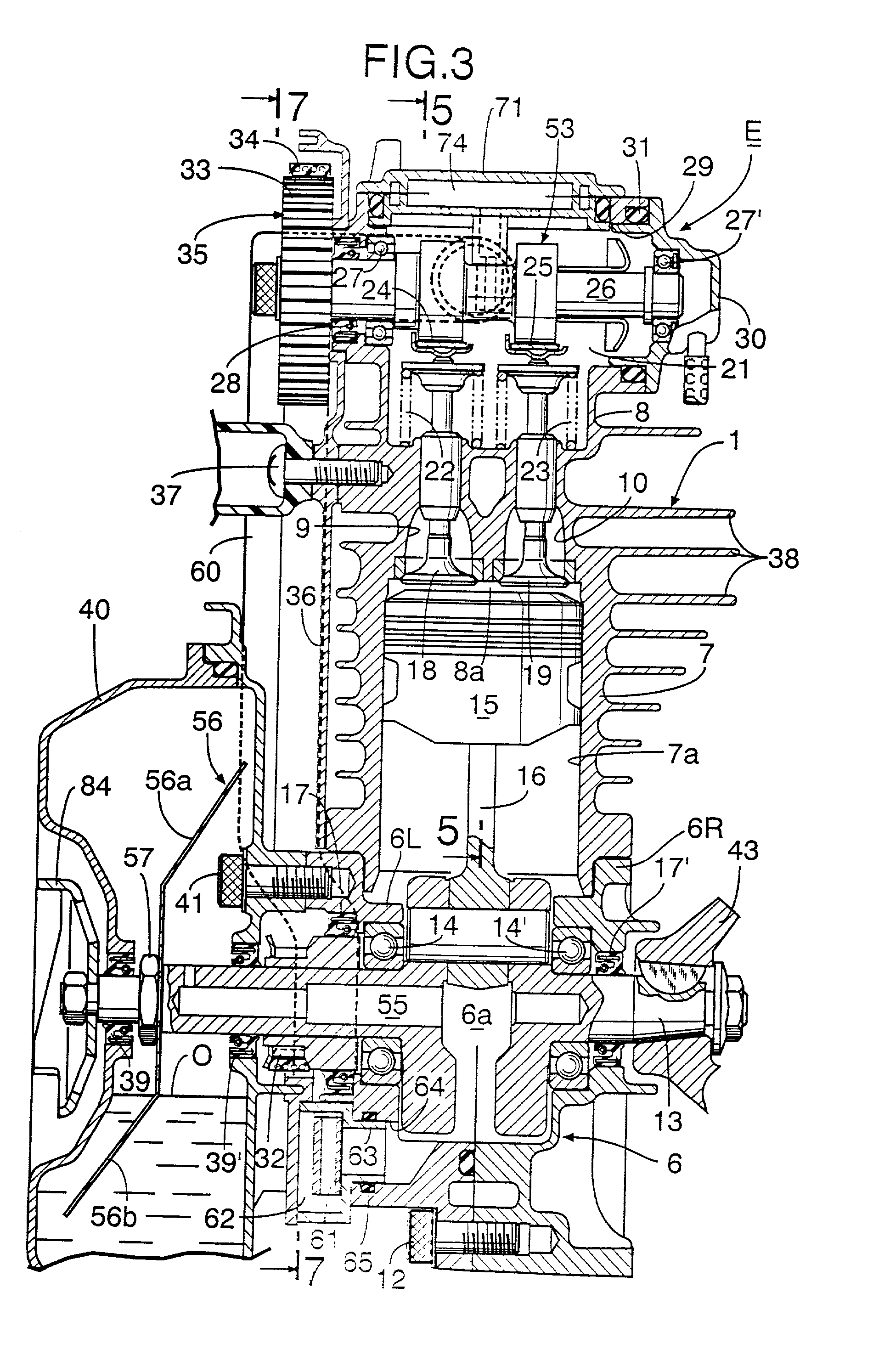
[0036] Firstly, the overall arrangement of the handheld type four-cycle engine is explained by reference to FIGS. 2 to 5.

[0037] As shown in FIGS. 2, 3 and 5, a carburettor 2 and an exhaust muffler 3 are attached to the front and back respectively of an engine main body 1 of the above-mentioned handheld type four-cycle engine E, and an air cleaner 4 is attached to the inlet of the carburettor 2. A fuel tank 5 made of a synthetic resin is attached to the lower face of th...


PUM


Abstract

In a handheld type four-cycle engine, the lubricating system includes an oil tank placed outside an engine main body, a through hole providing communication between the oil tank and a crank chamber, an oil feed pipe placed outside the engine main body and providing communication between the crank chamber and a valve operation chamber of a cylinder head, an oil return pipe placed outside the engine main body and providing communication between the valve operation chamber and the oil tank, and a one-way valve for transferring oil from the crank chamber to the valve operation chamber side via the oil feed pipe. The side walls of the engine main body can thus be made thinner and the weight of the engine main body can therefore be reduced regardless of the presence of the oil feed pipe and the oil return pipe.

Description

[0001] 1. Field of the Invention[0002] The present invention relates to handheld type four-cycle engines which are mainly used as a power source for machines for portable operation such as trimmers. More particularly, it relates to improvement of a four-cycle engine that includes an engine main body, the engine body including a crankcase having a crank chamber, a cylinder block having a cylinder bore and a cylinder head having an intake port and an exhaust port; a crankshaft supported in the crankcase and housed inside the crank chamber; a piston fitted in the cylinder bore and connected to the crankshaft; an intake valve and an exhaust valve for opening and closing the intake port and exhaust port, the intake valve and exhaust valve being mounted to the cylinder head; a valve operation mechanism operable in association with the rotation of the crankshaft so as to open and close the intake valve and exhaust valve; and a power output or takeoff mechanism provided on one end of the cr...

Claims


Application Information

Patent Timeline
18 Oct 2001
Publication
US20010029921A1
IPC
F02B67/06; F01M1/04; F01M1/06; F01M9/06; F01M11/00; F01M11/02; F01M11/06; F02B63/02; F02B75/02; F02F1/24
CPC
F01M1/04; F01M9/06; F01M11/065; F02B63/02; F02B67/06; F02B2075/027; F02B2275/20
Inventors
ITO, KEITA; NISHIDA, TAKAO