

Heat and corrosion resistant steel pipe having multi-layered coating
- Summary
- Abstract
- Description
- Claims
- Application Information
AI Technical Summary
Problems solved by technology
Method used
Image

Examples
example 1
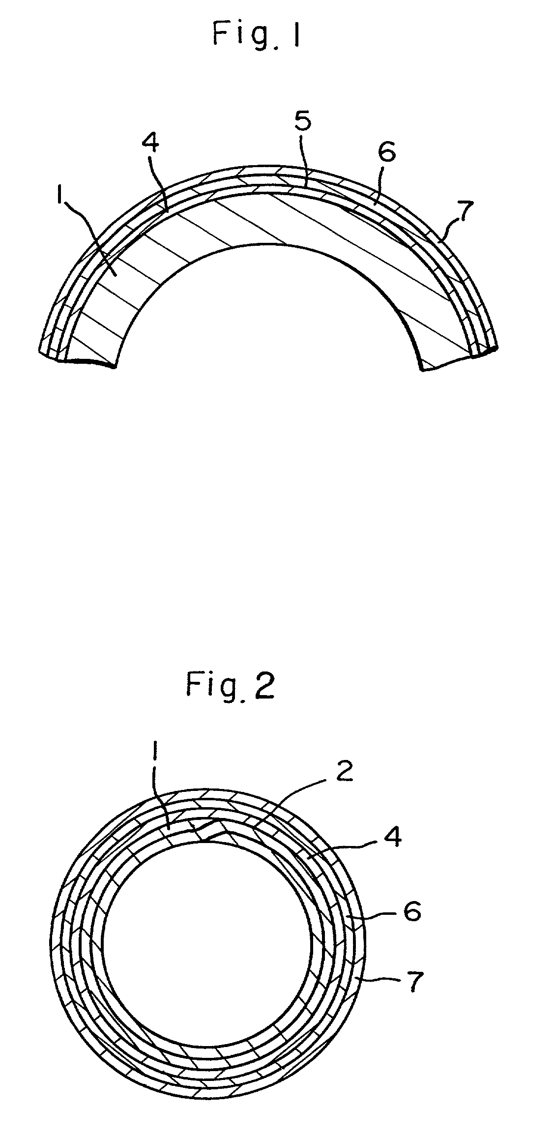
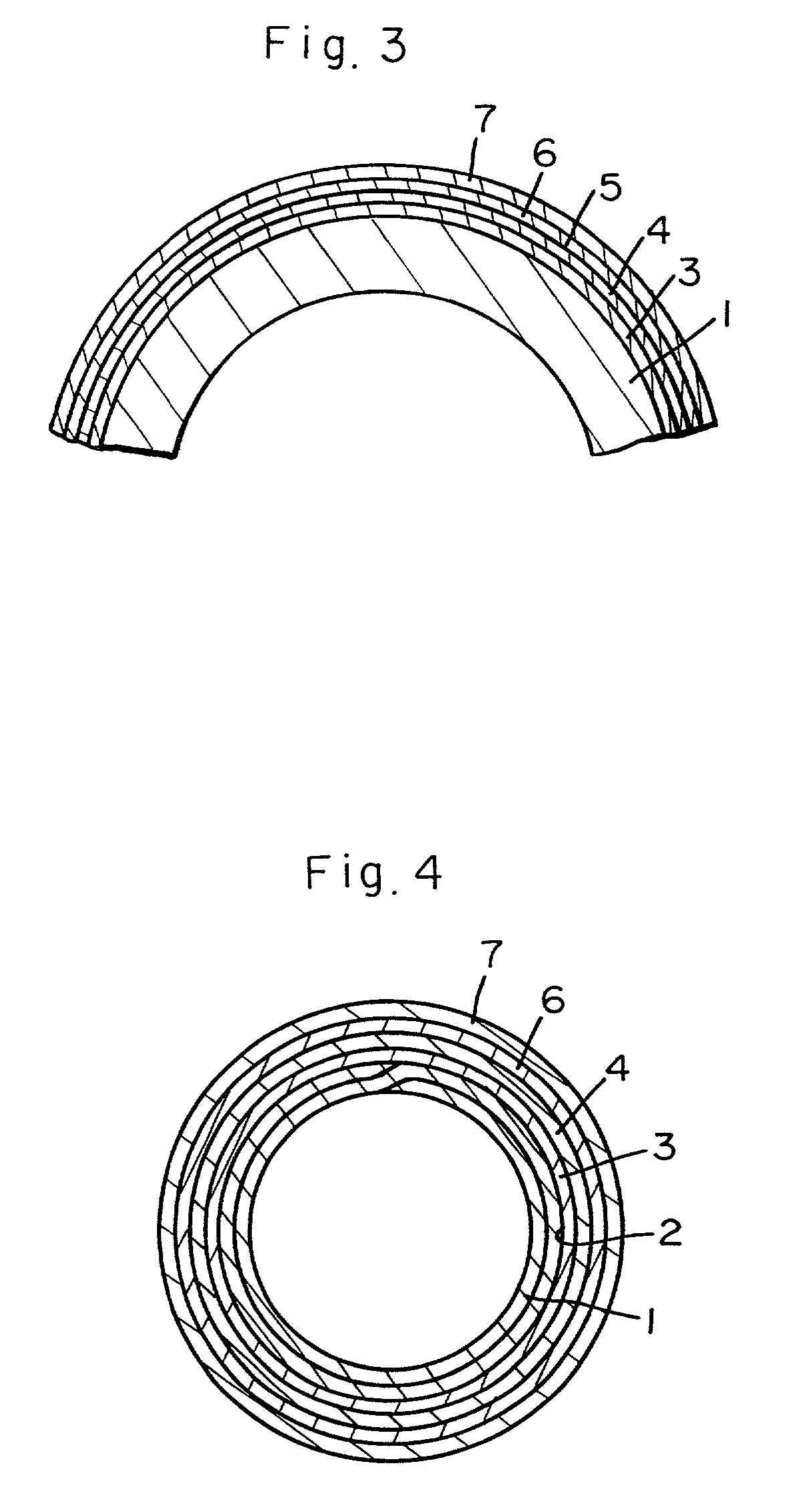
[0019] (1) Steel Pipe a
[0020] A double-wound steel pipe with having 8 mm outer diameter, 0.7 mm wall thickness and 330 mm length was prepared by using a hoop sheet made of SPCC and having copper plating layer of 3 um thickness on both surfaces.
[0021] (2) Formation of Zn--Ni Alloy Plating Layer
[0022] An alloy plating layer of 8 um thickness was formed by using a Zn--Ni alloy plating bath comprising a chloride bath (Zn-10MU, manufactured by Ebara-Udylite Co., Ltd.).
[0023] (3) Formation of Resin Layer
[0024] The steel pipe a formed with the Zn--Ni alloy plating layer obtained in (2) above was immersed in a paint prepared from an epoxy resin and a pigment dissolved in a solvent to apply resin coating and then heat-treated at 350.degree. C. for 60 sec to form an intermediate layer of an epoxy resin of about 5 um thickness. Then, it was immersed in a solution comprising polyvinyl fluoride coating dispersed in diethyl phthalate to apply polyvinyl fluoride and then heat-dried at 250.degree. ...
example 2
[0029] (1) Steel Pipe b
[0030] Electro-welded pipe made of STPG 38, with 8 mm outer diameter, 0.7 mm wall thickness and 330 mm length.
[0031] (2) Zn--Ni alloy plating Layer and the resin layer were formed in the same procedures as those in Example 1 and various tests were applied in the same manner as in Example 1. The results are shown in Table 1.
example 3
[0032] Formation of Zn--Ni alloy plating layer and chromate treatment.
[0033] After forming a Zn--Ni alloy plating layer by using a steel pipe a in the same manner as in Example 1, a chromate layer was formed by dipping in a chromate processing solution (Zn-80YMU, manufactured by Ebara-Udylite Co., Ltd.) at a solution temperature of 50.degree. C. for 20 sec.
[0034] (2) Subsequently the resin film was formed in the same procedures as in Example 1 and various tests were conducted in the same manner as in Example 1. The results are shown in Table 1.
PUM
| Property | Measurement | Unit |
|---|---|---|
| Fraction | aaaaa | aaaaa |
| Thickness | aaaaa | aaaaa |
| Thickness | aaaaa | aaaaa |
Abstract
Description
Claims
Application Information