Magnetic levitation motor and method for manufacturing the same

a technology of magnetization and levitation motor, which is applied in the direction of magnetic circuit rotating parts, magnetic circuit shape/form/construction, mechanical equipment, etc., can solve the problems of increasing the length of the rotor shaft, reducing the critical speed of the shaft, and complicated winding work

Inactive Publication Date: 2001-10-18
SANKYO SEIKI MFG CO LTD
View PDF0 Cites 42 Cited by
  • Summary
  • Abstract
  • Description
  • Claims
  • Application Information

AI Technical Summary

Benefits of technology

[0011] Before the stator core sections are joined together to form the first stator core, the first winding and the second winding are wound around the salient pole section of each of the individual stator core sections. As a result, the winding work is substantially facilitated.
[0012] In accordance with another embodiment of the present invention, a magnetic levitation motor has two of the magnetic levitation motor sections, in which two of the first stator cores are disposed in parallel with each other in the axial direction. As a result, the motor output is increased.
[0014] In accordance with one embodiment of the present invention, the second stator core is formed from a circular ring section and a plurality of salient poles radially extending toward a center of rotation from the circular ring section. The base section of the stator core section has abutting side faces. The abutting side faces of the base sections of a plurality of the stator core sections are connected together to form the circular ring section of the second stator core, and the non-magnetic section is disposed in every other one of the abutting end faces between the base sections. As a result, a magnetic bearing can be provided independently of a magnetic levitation motor. The second stator core in the magnetic bearing section prevents interference among levitation control magnetic fluxes. As a consequence, magnetic fluxes that hinder the generation of magnetic levitation force are reduced, and the magnetic levitation force is effectively obtained.

Problems solved by technology

However, in this structure, the magnetic bearings are disposed on both sides of the motor section, and therefore the length of the rotor shaft increases, and the critical speed of the shaft lowers.
In addition, the two types of windings need to provide on many salient poles, and winding works are complicated.
In particular, in the case of a stator for an inner rotor type magnetic levitation motor, gaps between tips of the salient poles are narrow, which makes the winding work more difficult and makes it more difficult to increase the line occupancy factor.
Also, a stator of a magnetic bearing that is used with a magnetic levitation motor has the same problems as described above.
Namely, the wiring work is difficult, and the magnetic bearing has a characteristic problem in which interference between the magnetic poles occurs.

Method used


Image

  • Magnetic levitation motor and method for manufacturing the same
  • Magnetic levitation motor and method for manufacturing the same
  • Magnetic levitation motor and method for manufacturing the same

Examples


Embodiment Construction

[0032] Magnetic levitation motors in accordance with various embodiments of the present invention are described below with reference to the accompanying drawings. First, a basic structure of a hybrid magnetic levitation motor and a principle of levitation will be described.

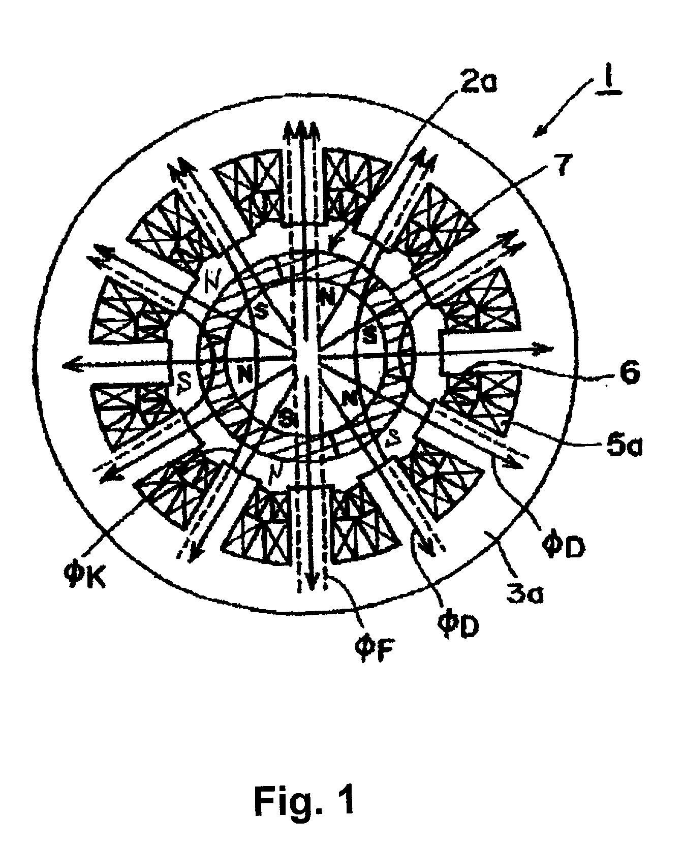
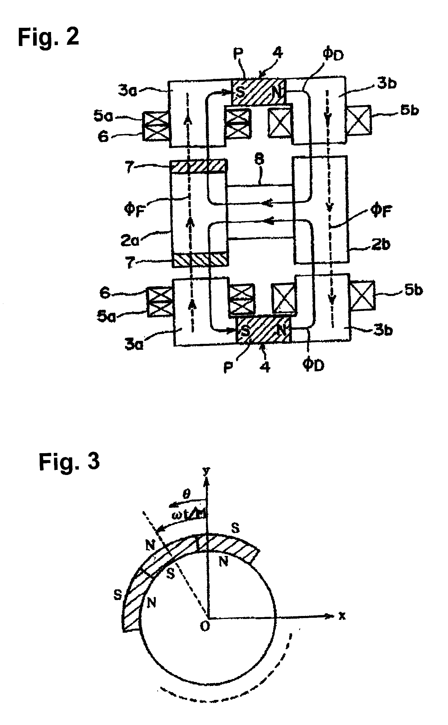
[0033] FIGS. 1 and 2 show a magnetic levitation motor 1 having rotors 2a and 2b, stators 3a and 3b disposed opposing to and around the external periphery of the rotors 2a and 2b, a direct current magnetic field generation device 4 that generates a magnetic flux spreading in a radial direction from the rotor 2a to the stator 3a, first stator windings 5a and 5b that generates a levitation control magnetic flux for controllably levitating the rotor, a second stator winding 6 for generating a rotation force acting on the rotor, and a plurality of permanent magnets 7 provided on the rotor 2a. A motor and a magnetic bearing are formed between the rotor 2a equipped with the permanent magnet 7 and the stator 3a. Also, mag...


PUM


Abstract

A magnetic levitation motor includes a rotor and a stator disposed opposite to the rotor. The rotor has a main body formed from a magnetic member and a permanent magnet attached to a peripheral surface of the main body. The stator has a first stator winding that generates a levitation control magnetic flux for controllably levitating the rotator body, a second stator winding that generates a rotation magnetic flux for rotating the rotator body and a stator core having the first stator winding and the second stator winding. A direct current magnetic field generation device is provided to generate a magnetic flux radially spreading from the rotor to the stator. The stator core is formed from a plurality of individual stator core sections. Each of the individual stator core sections has a base section and a salient pole section extending from a central section of the base section. The first winding and the second winding are wound around the salient pole section of each of the individual stator core sections. Then, the stator core sections are joined together to form the stator core.

Description

[0001] 1. Field of the Invention[0002] The present invention relates to a magnetic levitation motor having a stator winding for controllably levitating a rotor and another stator winding for generating a rotation magnetic flux, and a method for manufacturing the same.[0003] 2. Description of Related Art[0004] Contact-type bearings are widely used. In addition, non-contact type magnetic bearings are also gaining popularity. A typical magnetic bearing uses a magnetic force to levitate a rotor member such as a rotor shaft and supports the rotor member in a non-contact manner. By the use of the magnetic bearing, the coefficient of friction of the bearing section becomes substantially zero (0), which makes a high-speed rotation possible. Also, the magnetic bearing does not need lubrication oil. This allows the use of the magnetic bearing under special conditions. For example, the magnetic bearing can be used at a high temperature or a low temperature, in vacuum and the like. Furthermore,...

Claims


Application Information

Patent Timeline
Patent Type & Authority Applications(United States)
IPC IPC(8): H02K1/14F16C39/06H02K1/27H02K7/09H02K41/02
CPCF16C32/0465F16C32/0493H02K7/09F16C2380/26H02K1/14H02K1/27H02K41/02
Inventor KANEBAKO, HIDEKI
Owner SANKYO SEIKI MFG CO LTD
Why Eureka
Try Eureka