Motor controller power switch arrangement

a technology for motor controllers and power switches, applied in the direction of motor/generator/converter stoppers, electronic commutators, dynamo-electric converter control, etc., can solve the problems of increased electrical inductance, increased physical space and electrical conductors, and other switching problems

Inactive Publication Date: 2001-10-18
BAUM MATTHEW C
View PDF0 Cites 9 Cited by
  • Summary
  • Abstract
  • Description
  • Claims
  • Application Information

AI Technical Summary

Problems solved by technology

However, these arrangements have in the past required greater physical space as well as larger electrical conductors for their interco

Method used


Image

  • Motor controller power switch arrangement
  • Motor controller power switch arrangement
  • Motor controller power switch arrangement

Examples


Embodiment Construction

[0028] General

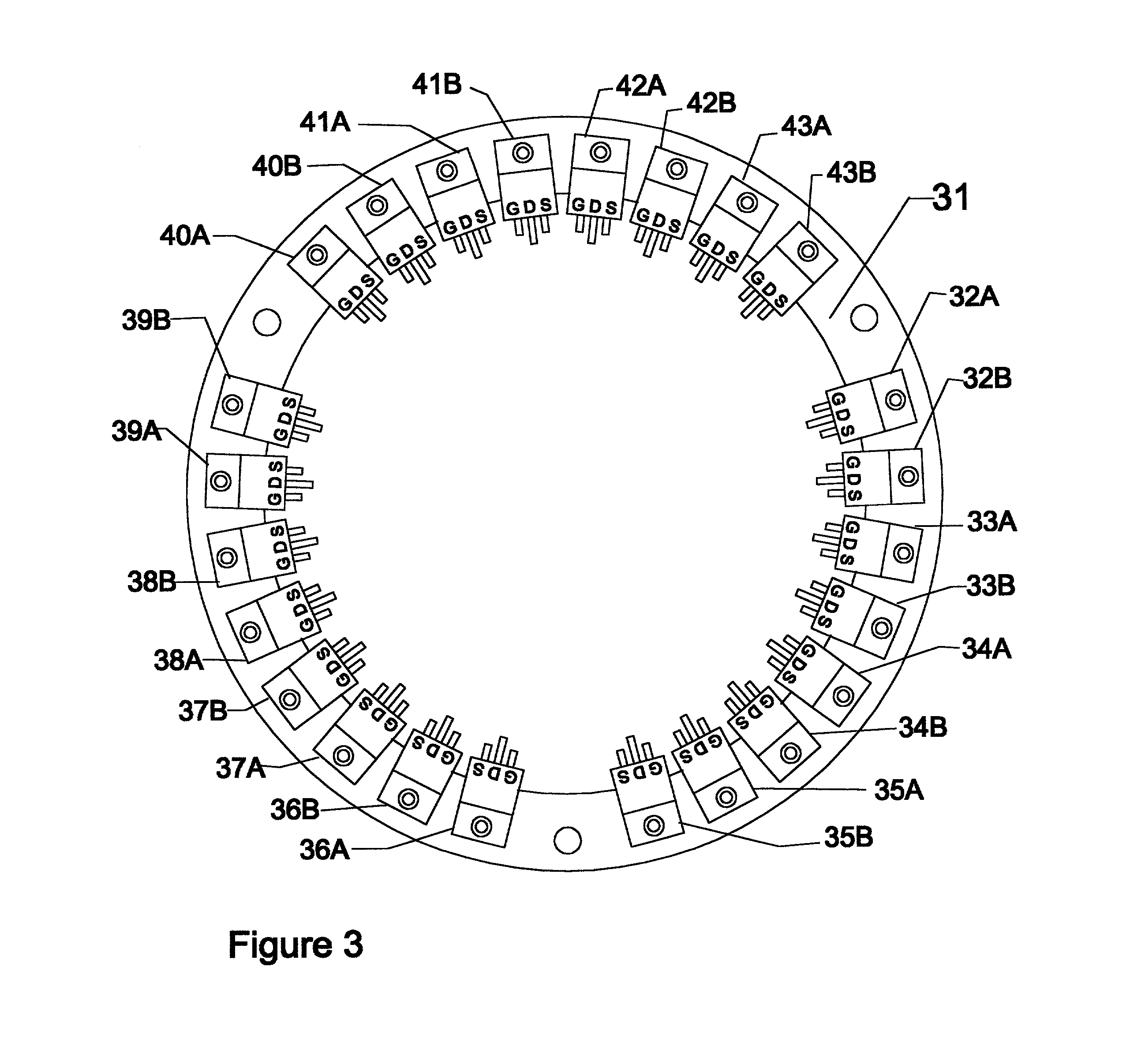
[0029] The present invention is concerned primarily with advantages which accrue from preferred physical arrangements of the power circuits for an inverter. A secondary benefit allows for the measurement of the current and power in the various controlling electronic switches, and for the control by fine adjustment of these switches so as to achieve various optimizations.

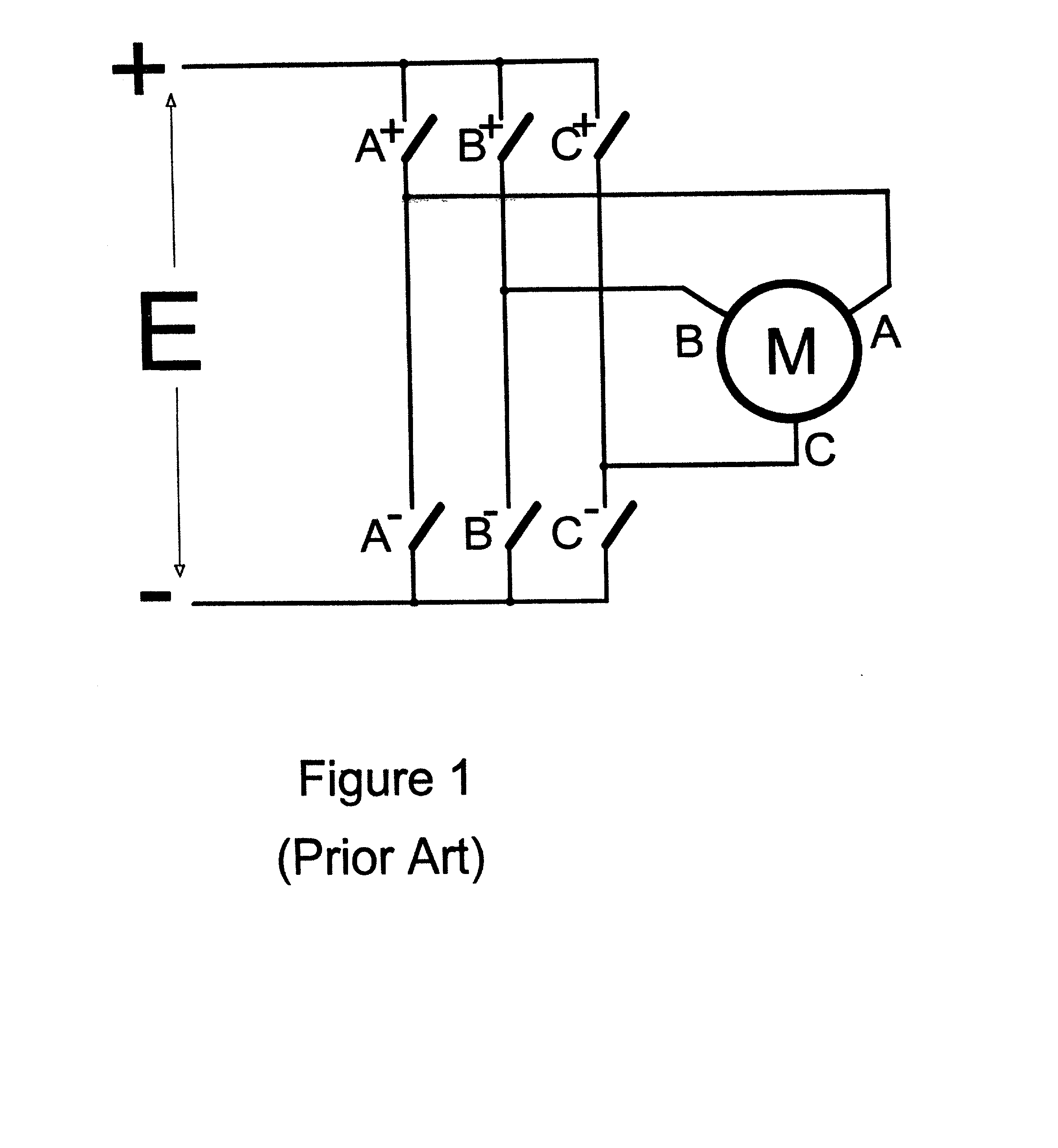
[0030] An inverter is required whenever DC (direct current) is used as the power source to operate an AC (alternating current) motor. Modern inverters employ semiconductor power electronic switches, under various types of control, to accomplish this conversion.

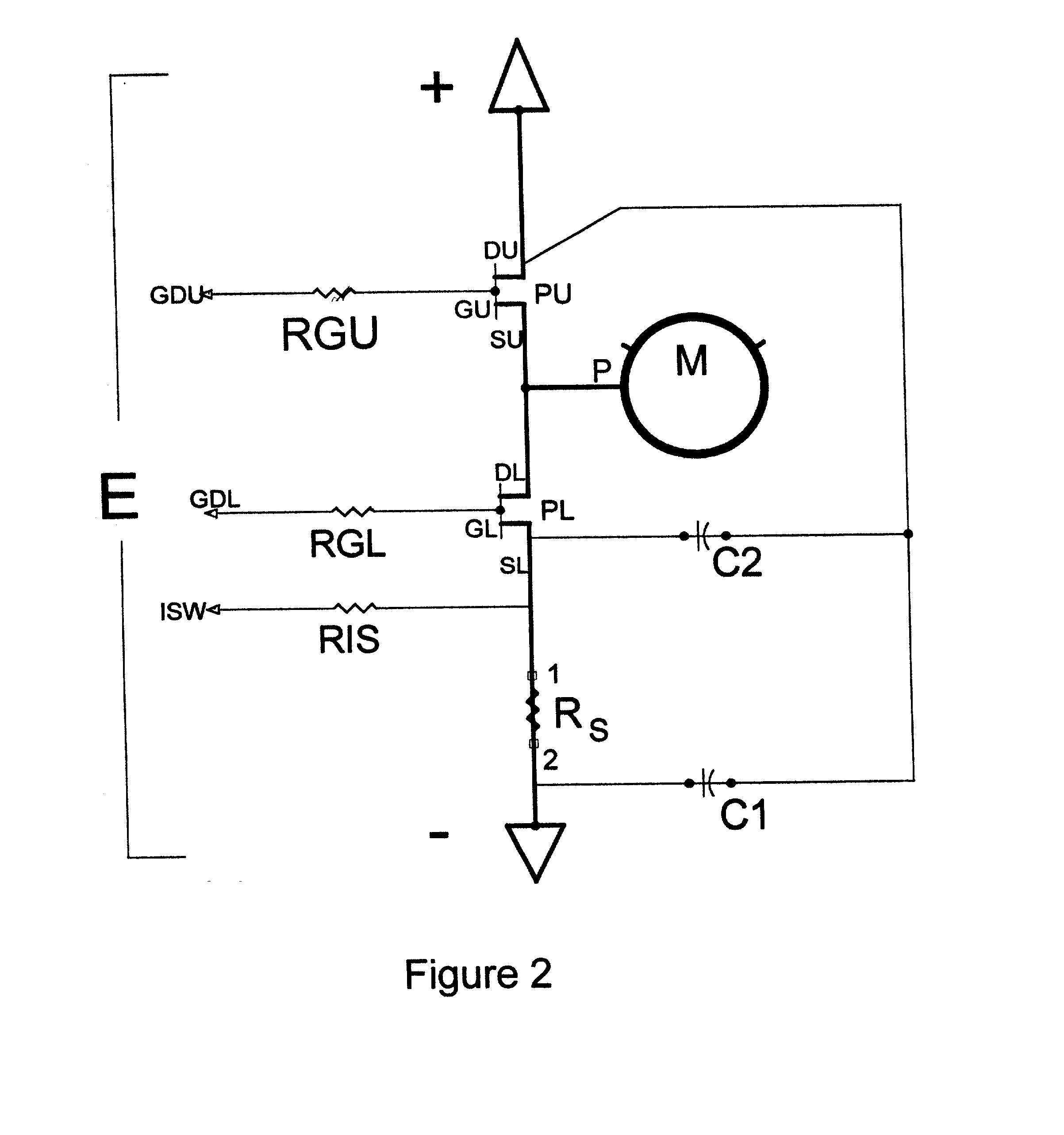
[0031] The present invention revolves about the arrangement of the power semiconductors and circuits in such inverters, as well as the provision of signals to the control apparatus for optimally "fine tuning" the system to achieve certain performance enhancements.

[0032] Typical Power Circuitry

[0033] The power switching portion of a typical inverte...


PUM


Abstract

A polyphase inverter employs multiple power semiconductor switches both for its operation and to distribute the current and heat loads for improved operation and cooling. The inherently high currents required for motor operation are divided among a plurality of smaller conductors and semiconductor switches, making a printed wiring board feasible both for power distribution and for control. The approach also permits shorter path lengths to the switches, reduced inductance, faster possible operation of the power switches, and reduced transient activity outside of the immediate switch area. Signals derived from various power points can enable the controller to assess actual current and power distribution and to apportion losses appropriately, or to limit total power output should the losses be deemed excessive.

Description

[0001] This application is a continuation in part of application Ser. No. 09 / 392,402 filed on Sep. 9, 1999.[0002] The present invention relates to apparatus used to drive a multi-phase motor from a direct current source. In particular it considers not the detailed circuitry, but rather the method and arrangement of the power components and electrical switches used.[0003] In the design of inverters for operating multi-phase motors from a DC power source, various types of solid-state or semiconductor switches are employed. Although modern semiconductor switches, such as MOS-FETs have very low losses, the problems caused by the heat losses of the switching devices cannot be avoided when motors of even modest power are controlled.[0004] Traditionally this problem has been solved by employing large heat sinks. These require space that is not always available. Alternatively, liquid cooling has been successful in some cases, but the physical problems of large power conductors used to conne...

Claims


Application Information

Patent Timeline
IPC IPC(8): H02P6/00
CPCH02P6/00
Inventor BAUM, MATTHEW C.
Owner BAUM MATTHEW C
Why Eureka
Try Eureka