

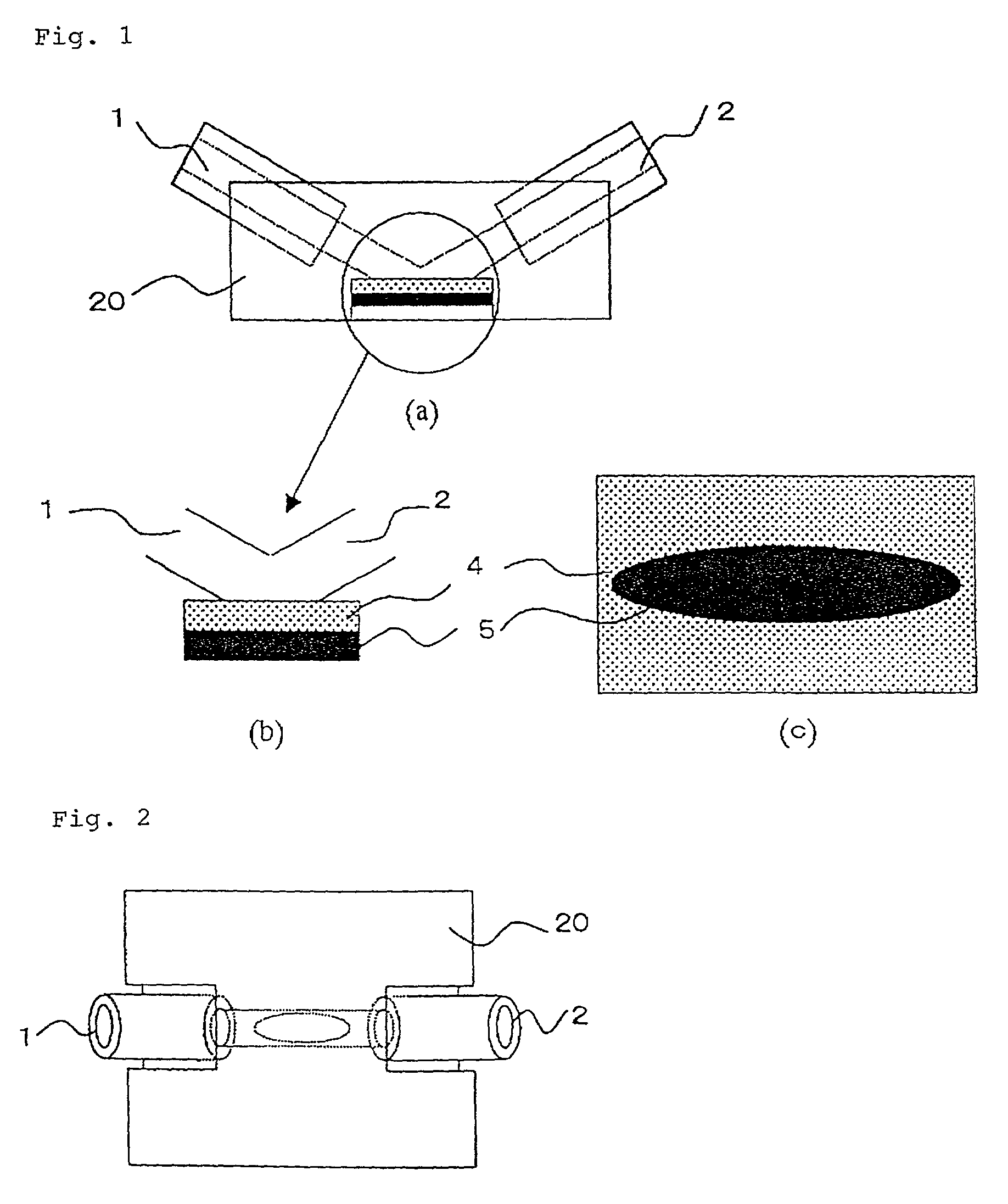
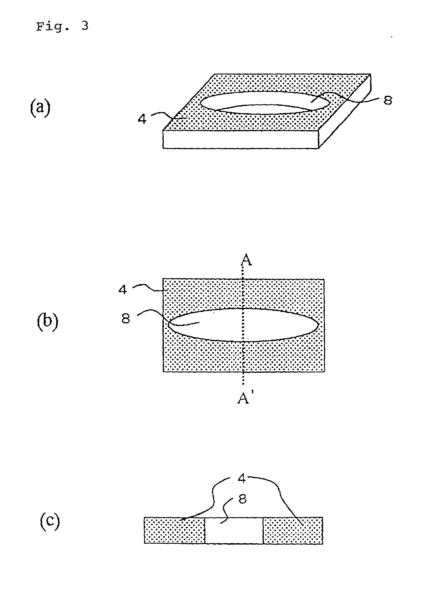
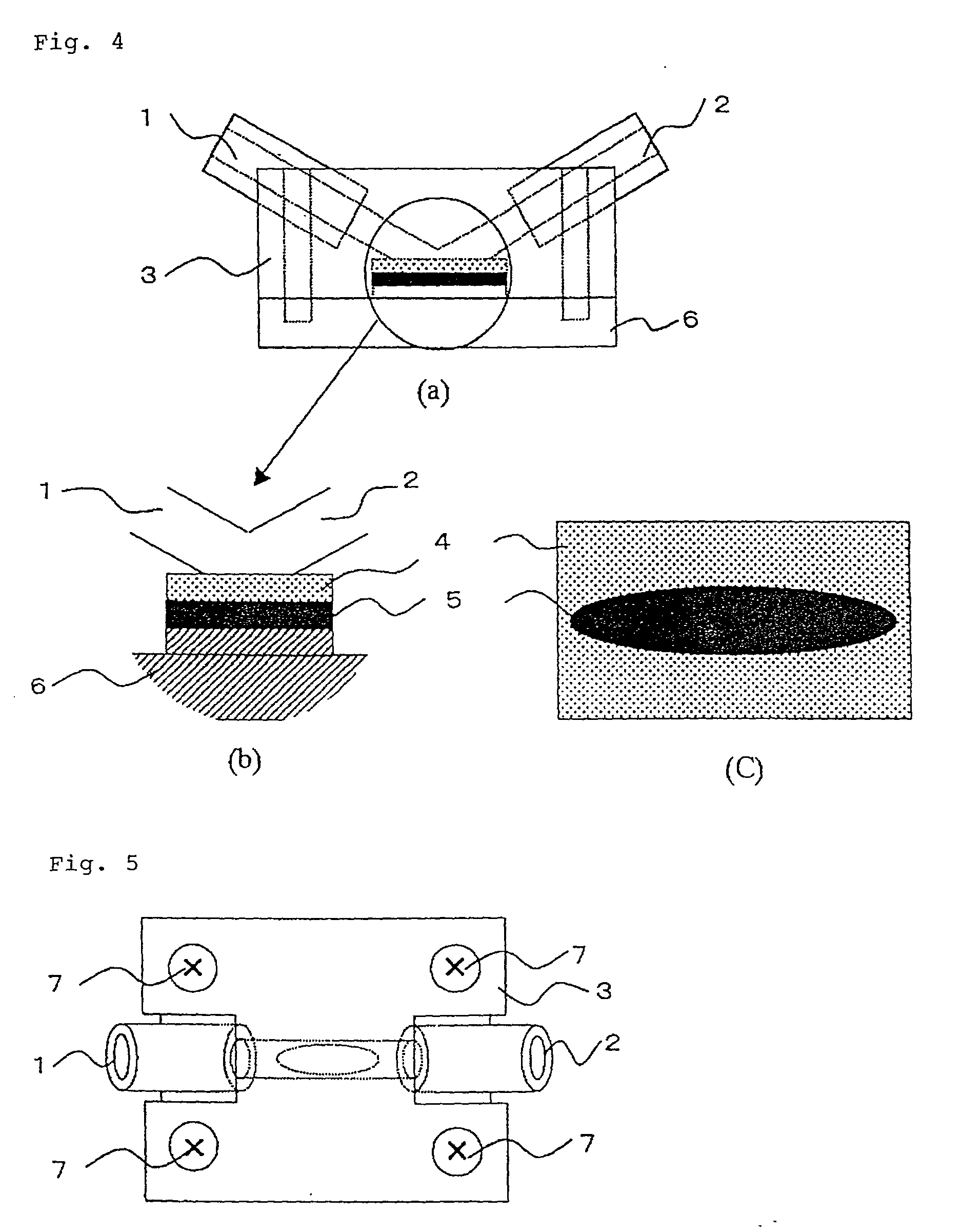
Measuring device for liquid sample and method for measuring liquid sample
- Summary
- Abstract
- Description
- Claims
- Application Information
AI Technical Summary
Benefits of technology
Problems solved by technology
Method used
Image

Examples
example 1
[0097] In this example, four types of devices for measuring a liquid sample having the structure shown in FIG. 1 were manufactured. Each device for measuring a liquid sample had one of the following sensors.
[0098] a) Glucose sensor
[0099] b) Lactate sensor
[0100] c) Urea sensor,
[0101] d) Urate sensor.
[0102] Angles of the liquid sample inlet and outlet channels to the surface of the sensor 5 were 30.degree.. Dimensions of the liquid sample inlet and outlet channels were as illustrated in FIGS. 11 and 12.
[0103] Using the above devices, a liquid-sample collection cell was attached to an upper arm of a male adult (age: 34 years, weight: 68 kg) and then glucose, lactate, urea and urate levels in body fluid (suction effusion fluid collected by vacuum suction) were determined at every 10 min for 2 hours while determining the levels of these components using a conventional laboratory test device (Trade name: Hitachi Automatic Measuring Device 7050) under the same conditions. Values thus obtai...
example 2
[0104] A device for measuring a liquid sample comprising three types of sensors, i.e, a glucose, a lactate and an urea sensors, with the structure shown in FIG. 8 was manufactured. Angles of the liquid sample inlet and outlet channels to the surface of the sensor 5 were 30.degree.. Dimensions of the parts except the sensor were as illustrated in FIGS. 11 and 12.
[0105] Using the above device, a liquid-sample collection cell was attached to an upper arm of a male adult (age: 34 years, weight: 68 kg) and then glucose, lactate and urea levels in body fluid (suction effusion fluid collected by vacuum suction) were determined at every 10 min for 2 hours while determining the levels of these components using a conventional laboratory test device (Trade name: Hitachi Automatic Measuring Device 7050) under the same conditions. Values thus obtained for each component were subject to regression analysis to estimate a correlation for evaluation. The results are shown in Table 2. The measuring d...
example 3
[0106] A device for measuring a liquid sample with the structure shown in FIG. 4 was manufactured. The sensor was a glucose sensor. An antifouling layer was formed using one of the following four polymers on the whole surface of the area to be in contact with a liquid sample within the device except the surface of the sensor 5, e.g., the inner wall of the liquid sample inlet channel, the inner wall of the liquid sample outlet channel and the opening inner wall of the elastic member 4 to provide four types of devices for measuring a liquid sample. Dimensions of the parts in the device for measuring a liquid sample were as illustrated in FIGS. 11 and 12.
[0107] Materials of the Antifouling Layer
[0108] a) 1H,1H-perfluorooctyl polymethacrylate,
[0109] b) 1H,1H,2H,2H-perfluorodecyl polyacrylate,
[0110] c) 1H,1H,2H,2H-perfluorodecyl polymethacrylate,
[0111] d) 1H,1H-perfluorooctyl polyacrylate.
[0112] A device without an antifouling layer was also manufactured as a control. Angles of the liqui...
PUM
| Property | Measurement | Unit |
|---|---|---|
| Time | aaaaa | aaaaa |
| Time | aaaaa | aaaaa |
| Time | aaaaa | aaaaa |
Abstract
Description
Claims
Application Information