Optical amplifiers with a simple gain/output control device

a control device and amplifier technology, applied in the field of optical fiber amplifiers, can solve the problems of low frequency modulation, wdm technology suffers from unwanted effects, and variation in output power, and achieves the effects of automatic suppression of power transients, minimizing the influence of amplifier ase noise, and fast control of amplifier gain or total output power

Inactive Publication Date: 2001-11-15
II VI DELAWARE INC
View PDF0 Cites 28 Cited by
  • Summary
  • Abstract
  • Description
  • Claims
  • Application Information

AI Technical Summary

Benefits of technology

[0008] Embodiments of the present invention can provide an optical amplifier and a control technique that overcomes the difficulties associated with known optical amplifiers. It is an advantage of this optical amplifier that it has a flexible controller that provides a choice of different control parameters. It is also an advantage of this optical amplifier that it automatically suppresses power transients by fast control of the amplifier gain or the total output power. It is further an advantage of this optical amplifier that the controller minimizes the influence of amplifier ASE noise.

Problems solved by technology

This WDM technology suffers from unwanted effects, such as a variation in output power when the input signal power is constant (for example, due to aging of the amplifier or due to stresses in the amplifier), and cross talk between different channels, for example, when the input signal is modulated at a low frequency.
This low frequency modulation can be present, for example, due to the addition or dropping of some to the channels, or due to sudden loss of signal at certain wavelengths.
These unwanted effects have a negative influence on the power transients (i.e., fluctuations of output optical signal power) of surviving channels, which results in a poor performance of the signal transmission, expressed in an increased bit error rate (BER).
This approach also limits accuracy of gain control when signal power is small.
Finally, this approach does not compensate for amplifier noise, such as ASE (amplified spontaneous emission).
This approach is even less flexible than the all-electronic approach described above, because any change in power or gain control requirements requires the change in optical components.

Method used


Image

  • Optical amplifiers with a simple gain/output control device
  • Optical amplifiers with a simple gain/output control device
  • Optical amplifiers with a simple gain/output control device

Examples


Embodiment Construction

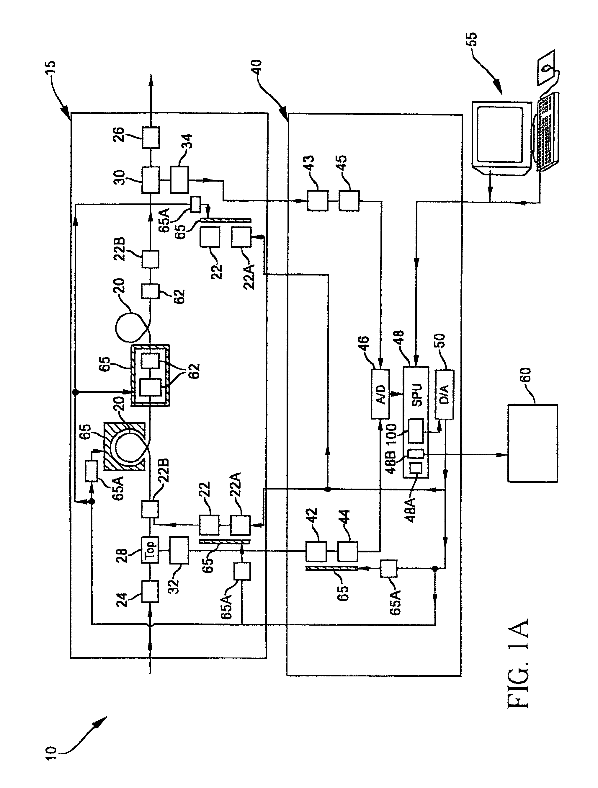
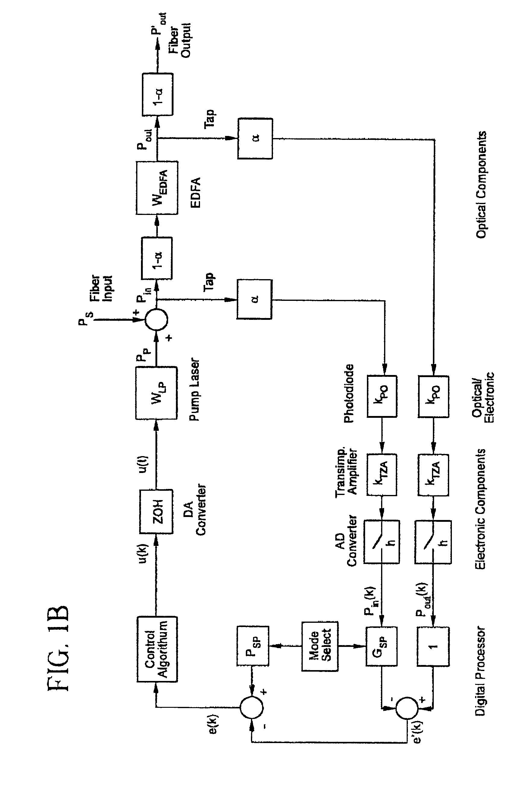
[0016] FIGS. 1A and 1B illustrate an embodiment of an improved optical fiber amplifier 10. This optical fiber amplifier 10 includes an optical system 15 comprised of an optical gain medium 20, for example a rare-earth doped fiber and at least one pump source 22, such as a laser diode, driven by a pump drive unit 22A coupled via a coupler 22B to the optical gain medium 20. The optical system further includes an input port 24 for an optical signal entering the gain medium 20, an output port 26 for an out-going signal and two optical taps 28 and 30. The tap 28 is an input optical signal tap 28 and is connected to a first optical detector 32. The tap 28 is located either downstream of the input port 24, but in front of the gain medium 20, or, alternatively, may form a part of an input port 24 or the coupler 22B. The tap 30 is an output optical signal tap and is connected to a second optical detector 34. The tap 30 is located downstream of the gain medium 20 in front of the output port 2...


PUM


Abstract

An optical fiber amplifier includes an optical system and an electronic controller. The optical system includes: an optical gain medium; at least one pump source coupled to the optical gain medium; an input port for in-coming signal; and an output port for an out-going signal. It also includes an input optical signal tap coupled to a first optical detector; and an output optical signal tap coupled to a second optical detector. The electronic controller is adapted to utilize inputs received from the tabs to control optical power provided by the pump source. The controller includes a user interface that allows a user to control at least one of the following available functions: desired amplifier gain value; amplifier output power value; ASE noise compensation.

Description

CROSS-REFERENCE TO A RELATED APPLICATION[0001] Reference is made to commonly assigned copending patent application serial number 60 / 196,784, filed Apr. 13, 2000 in the name of Gerrish et al. and entitled "OPTICAL AMPLIFIERS WITH A SIMPLE GAIN / OUTPUT CONTROL DEVICE". Reference is also made to patent application filed concurrently in the name of Gerrish et al., entitled "METHOD FOR CONTROLLING PERFOMANCE OF OPTICAL AMPLIFIERS". Both applications are incorporated by reference, herein.[0002] This invention relates to optical amplifiers and more specifically to automatic gain and output power control of Optical Amplifiers.[0003] In recent years optical amplifier modules have undergone considerable transformation. Increased demand for more data transfer resulted in development of wavelength division multiplexing (WDM) technology, which allows more data to be transmitted over one fiber by increased channel count (i.e., a larger number of narrower wavelength ranges within the same predeterm...

Claims


Application Information

Patent Timeline
Patent Type & Authority Applications(United States)
IPC IPC(8): H01S3/06H01S3/067H01S3/10H01S3/102H01S3/13H01S3/131H04B10/07H04B10/2507H04B10/293H04B10/294H04B10/564H04B10/572H04J14/00H04J14/02
CPCH01S3/06754H01S3/10015H01S3/1301H04B10/2931H01S3/1312H01S2301/02H01S3/1305H01S3/10023H01S3/094011H01S3/10013H01S2301/04H01S3/13013
Inventor GERRISH, KEVIN S.LELIC, MUHIDIN
Owner II VI DELAWARE INC
Why Eureka
Try Eureka