Surface mount antenna and communication device including the same

a communication device and surface mount technology, applied in the structural form of resonant antennas, resonant antennas, protective material radiating elements, etc., can solve the problems of difficult to achieve a further reduction in the size of the antenna, difficult to set the difference between the resonance frequency in the fundamental mode and the resonance frequency in the high-order mode over a large range, and difficult to efficiently produce and provide an antenna with high performance and high reliability

Inactive Publication Date: 2001-12-06
MURATA MFG CO LTD
View PDF0 Cites 13 Cited by
  • Summary
  • Abstract
  • Description
  • Claims
  • Application Information

AI Technical Summary

Problems solved by technology

This makes it difficult to achieve a further reduction in the size of the antenna.
Thus, it is difficult to set the difference between the resonance frequency in the fundamental mode and the resonance frequency in the high-order mode over a large range.
Furthermore, it is difficult to precisely control the resonance frequency in the high-order mode by adjusting the perimeter (shape) of the cut-out 106, and thus it is difficult to efficiently produce and provide an antenna having high performance and high reliability.

Method used


Image

  • Surface mount antenna and communication device including the same
  • Surface mount antenna and communication device including the same
  • Surface mount antenna and communication device including the same

Examples


first embodiment

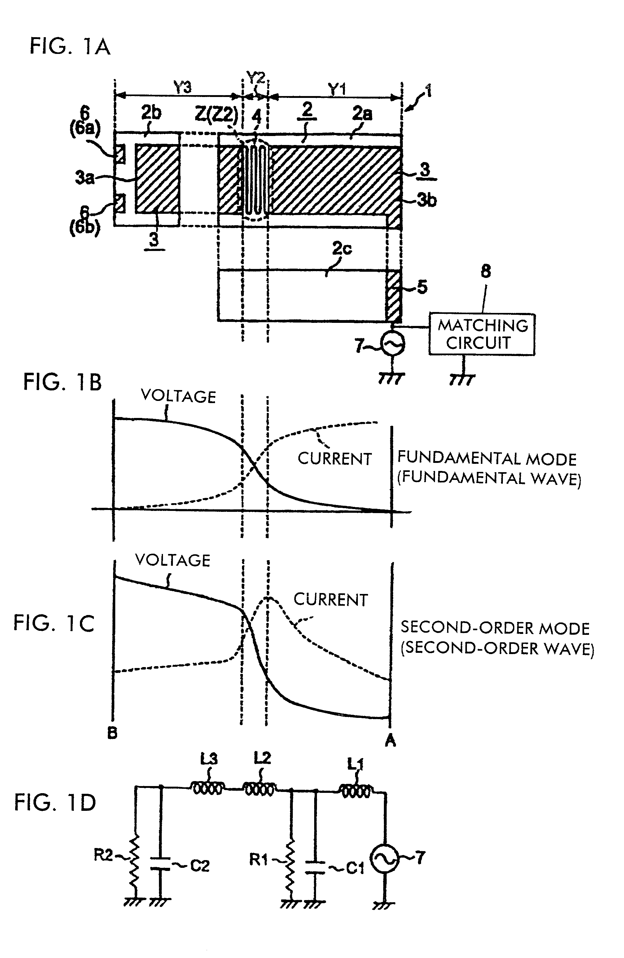
[0054] As shown in FIG. 1A, the feeding radiation electrode 3 is formed into the shape of a stripe extending from the upper surface 2a to the side face 2b of the dielectric substrate 2. A meander pattern 4, which characterizes the first embodiment, is formed locally in the feeding radiation electrode 3. An end 3a, on the left side of FIG. 1A, of the feeding radiation electrode 3 is formed to be electrically open and the end 3b on the right side is electrically connected to a feeding terminal 5 which extends from the right end 3b of the feeding radiation electrode 3 onto the side face 2c and further onto the bottom surface.

[0055] On the side face 2b of the dielectric substrate 2, fixed ground electrodes 6 (6a, 6b) are formed at locations spaced by gaps from the open end 3a of the feeding radiation electrode 3.

[0056] In practical applications, the surface mount antenna 1 is mounted on a circuit board of a communication device such that the bottom surface (not shown), opposite to the u...

second embodiment

[0085] FIG. 9B illustrates an equivalent circuit of the feeding radiation electrode 3 of the In FIG. 9B, L1 represents the series inductance component locally added in the maximum resonance current part Z1 in the fundamental mode by the meander pattern 10. L2 represents an inductance component in the part X2 having the small electrical length, wherein the inductance component L2 is smaller than the inductance component L1. L3 represents the series inductance component locally added in the maximum resonance current part Z2 in the second-order mode by the meander pattern 4, wherein the inductance component L3 is greater than the inductance component L2. L4 represents an inductance component in the part X4 having the small electrical length, wherein the inductance component L4 is smaller than the inductance component L3. C1 and C2 represent capacitance between the feeding radiation electrode 3 and ground, and R1 and R2 represent conduction resistance components of the feeding radiatio...

third embodiment

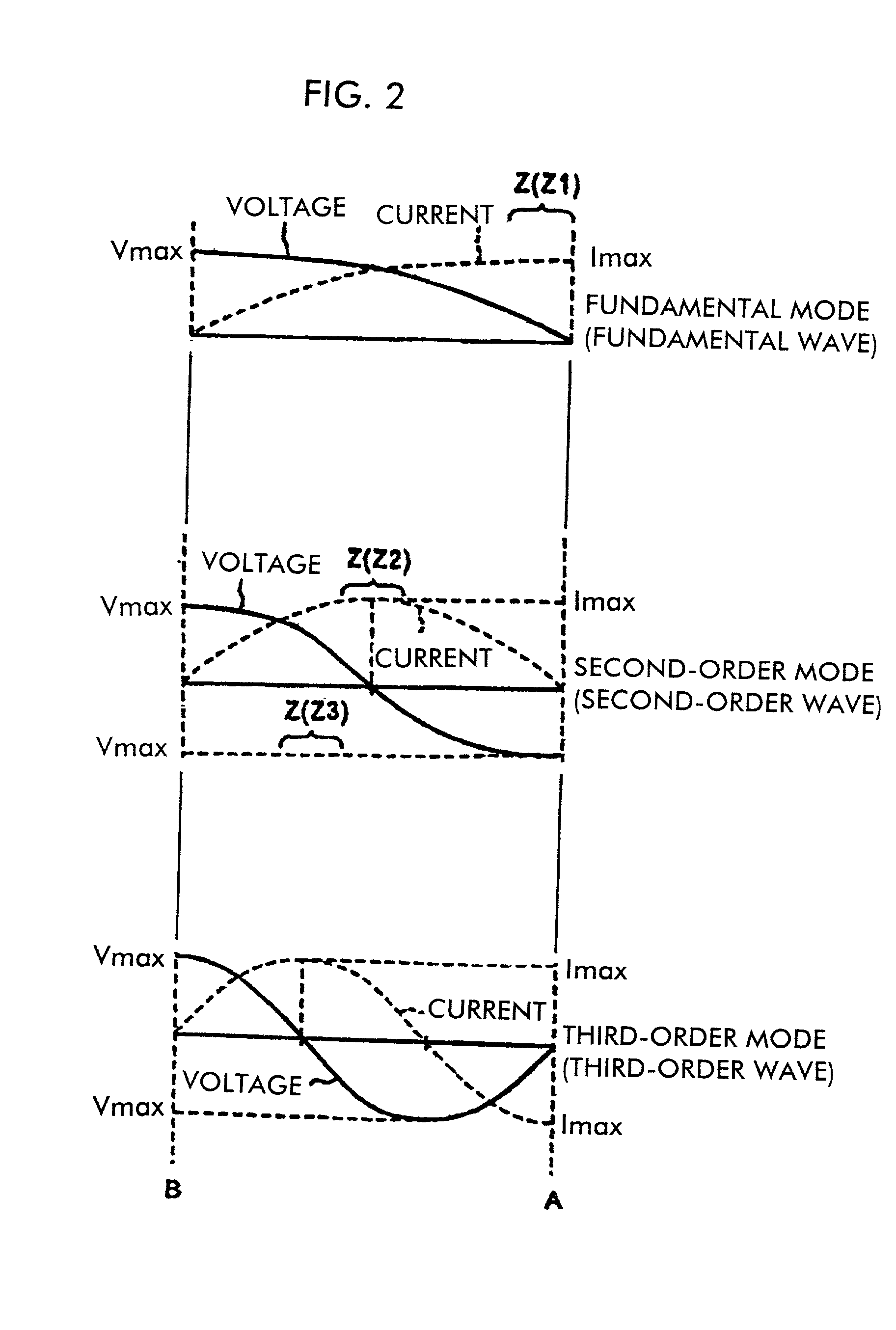
[0098] This is utilized in the third embodiment to locally form an equivalent series inductance component in one of or both of the maximum resonance current parts in the fundamental mode and the high-order mode. Specific examples of surface mount antennas 1 having such a structure are shown in FIGS. 12A, 12B, and 12C.

[0099] In each of the surface mount antennas 1 shown in FIGS. 12A, 12B, and 12C, an equivalent series inductance component is locally added in a maximum resonance current part Z (Z2) in the second-order mode. In the example shown in FIG. 12A, a side end of the strip-shaped feeding radiation electrode 3 is partially cut out so as to form a cut-out portion 13 in a maximum resonance current part Z (Z2) in the second-order mode, and a parallel capacitance electrode 14 is disposed in the cut-out part such that the parallel capacitance electrode 14 is spaced from the feeding radiation electrode 3 by a gap, thereby forming a parallel capacitance component C between the paralle...


PUM


Abstract

In a feeding radiation electrode of a surface mount antenna, a series inductance component such as a meander pattern is formed locally in a maximum resonance current part in a high-order mode (second-order mode) so as to locally form a series inductance component therein thereby making the maximum resonance current part have a greater electrical length per unit physical length than the other parts. This makes it possible to control the difference between the resonance frequency in a fundamental mode and the resonance frequency in the high-order mode over a large range. Furthermore, it is possible to vary the resonance frequency in the second-order mode independently of the resonance frequency in the fundamental mode by varying the number of lines or the line-to-line distance of the meander pattern thereby varying the value of the series inductance component. Thus, it is possible to easily and efficiently design a surface mount antenna having a frequency characteristic which satisfies requirements needed in multi-band applications without having to change the basic design.

Description

[0001] 1. Field of the Invention[0002] The present invention relates to a surface mount antenna capable of transmitting and receiving signals (radio waves) in different frequency bands and also to a communication device such as a portable telephone including such an antenna.[0003] 2. Description of the Related Art[0004] In recent years, it is needed to commercially provide a single terminal having a multi-band capability for use in plural applications such as GSM (Global System for Mobile communication systems), DCS (Digital Cellular System), PDC (Personal Digital Cellular telecommunication system), and PHS (Personal Handyphone System). To meet the above requirement, Japanese Unexamined Patent Application Publication No. 11-214917 discloses a multiple frequency antenna of the surface mount type capable of transmitting and receiving signals in different frequency bands.[0005] In this antenna, as shown in FIG. 22A, a dielectric member 105 is disposed on a ground plate 101, and a condu...

Claims


Application Information

Patent Timeline
Patent Type & Authority Applications(United States)
IPC IPC(8): H01Q21/30H01Q1/24H01Q1/38H01Q5/10H01Q5/314H01Q9/04H01Q13/08
CPCH01Q1/38H01Q9/0421H01Q5/378H01Q5/357H01Q9/0442H01Q5/00
Inventor NAGUMO, SHOJIKAWAHATA, KAZUNARITSUBAKI, NOBUHITOISHIHARA, TAKASHIONAKA, KENGO
Owner MURATA MFG CO LTD
Why Eureka
Try Eureka