Electronic assembly having high interconnection density

a technology of interconnection density and electronic assembly, which is applied in the association of printed circuit non-printed electric components, instruments, optical elements, etc., can solve the problems of reducing the service life affecting the operation of the removal system, and raising a problem

Inactive Publication Date: 2001-12-13
ALCATEL LUCENT SAS
View PDF0 Cites 4 Cited by
  • Summary
  • Abstract
  • Description
  • Claims
  • Application Information

AI Technical Summary

Benefits of technology

0004] An object of the invention is to remedy the above-mentioned problem by proposing an electronic assembly provided with a cooling device and also proposing interconnection means for the electronic module, the interconnection means being distinct from the cooling d

Problems solved by technology

The state of the art assembly raises a problem since it firstly prevents the module from providing interconnections at high density.
Secondly, the heat removal system that is provided is not sufficient since it is made in the printed circuit card, even through firstly the amount of heat to be removed is large and secondly the remo

Method used


Image

  • Electronic assembly having high interconnection density
  • Electronic assembly having high interconnection density

Examples


first embodiment

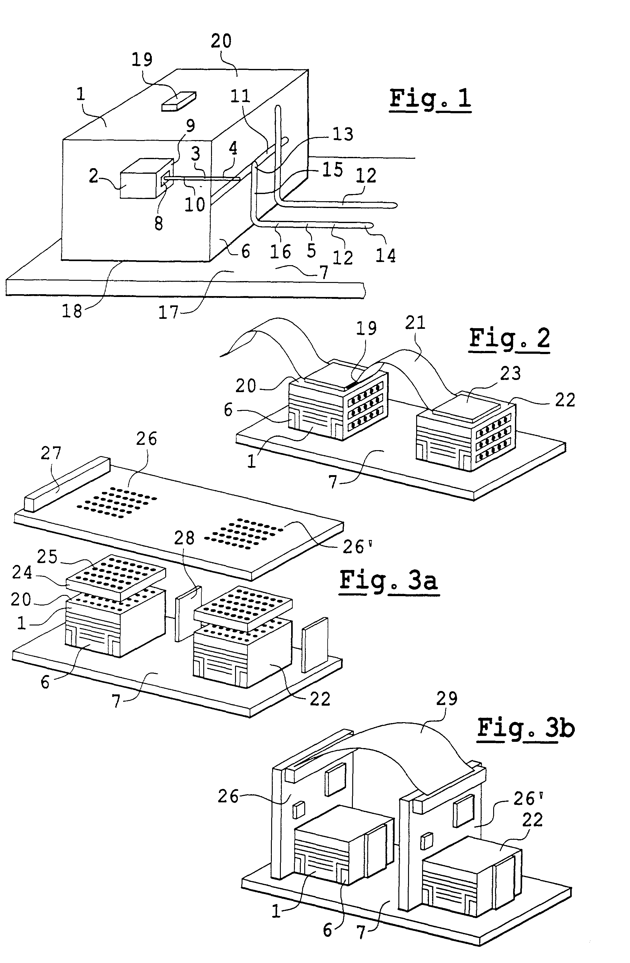
[0041] In FIG. 1, the interconnection means is a connector 19 mounted on a face 20 such that the face 20 is different from the face 18. In a first embodiment, the connector 19 is connected to a flexible printed circuit 21 to connect the module 1 to a second connector 23 on a second electronic module 22.

[0042] The second module 22 can be made in identical manner to the first electronic module 1, in which case it is likewise mounted on the top surface 17 of the soleplate 7. Under such circumstances, the second electronic module 22 also has an electronic assembly with heat removal such as 3.

[0043] In a variant, the second module 22 can be mounted on a substrate that is equivalent to that of the soleplate 7, for example so that the top faces of the modules 1 and 22 lie in a common plane.

second embodiment

[0044] In a second embodiment, as shown in FIG. 3a, the interconnection means is a contact matrix 24 comprising spring contacts 25, the contact matrix 24 being placed between a face such as the face 20 of the module 1 and a printed circuit card 26. The printed circuit card 26 can also be connected to the second module 22 as shown in FIG. 3a, for example.

third embodiment

[0045] In a third embodiment, as shown in FIG. 3b, the interconnection means is a matrix of contacts having spring contacts as shown in FIG. 3a, but also including second connection means. The second connection means comprise, for example, a printed circuit card 26' mounted on the module 22, and an intermediate flexible printed circuit 29 for connecting the printed circuit card 26 to the second printed circuit card 26'.

[0046] These printed circuit cards 26 and 26' can also have other connectors 27 for making connections with other elements. The card 26 is held to the module 1 in part by mounting the card 26 on a stiffener 28. For example, the card 26 can be screwed to the stiffener 28.

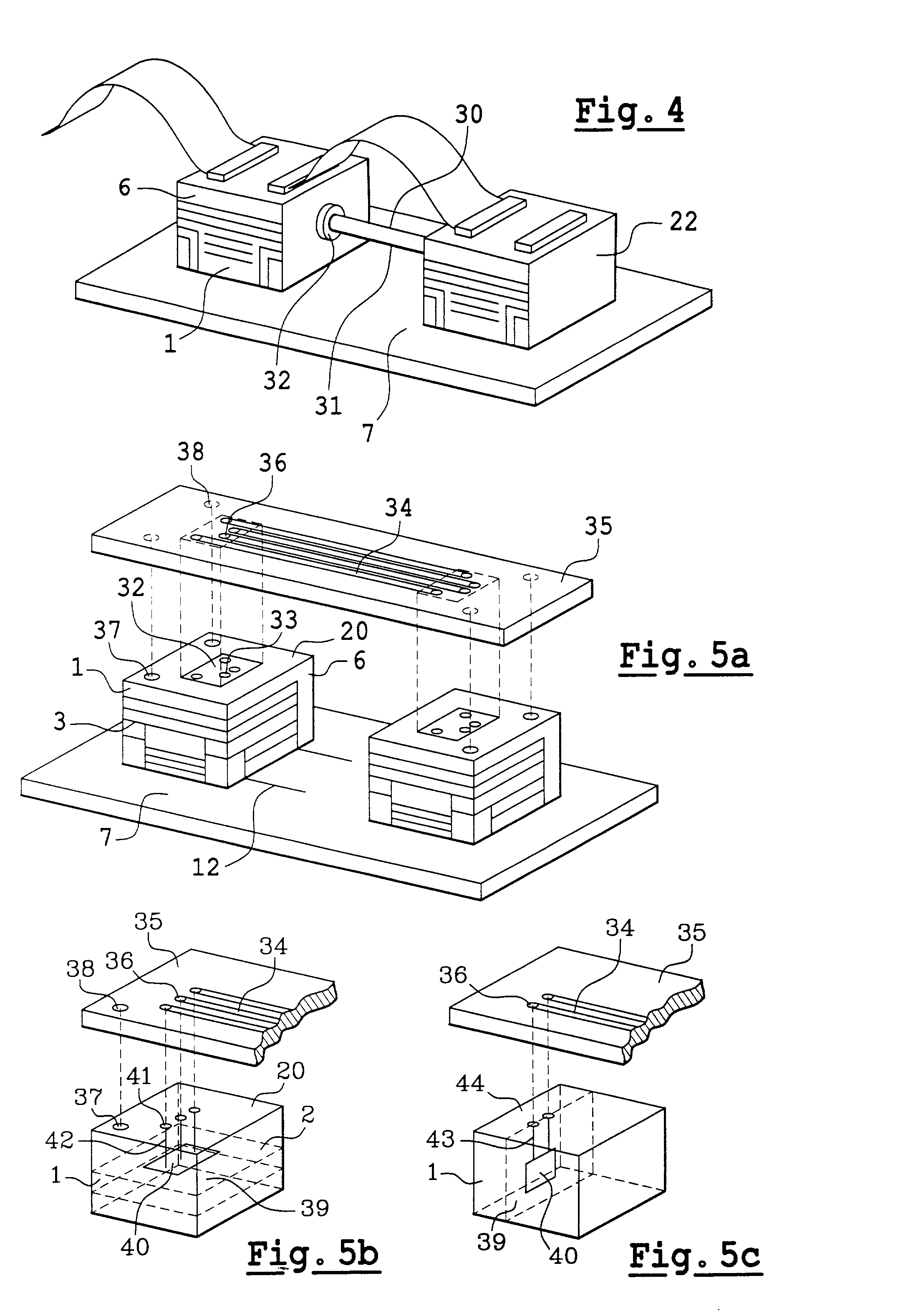
[0047] In the fourth embodiment as shown in FIG. 4, the interconnection means can be optical interconnection 30. In this fourth embodiment, the optical interconnection 30 comprises an optical fiber 31 and a first optical connector 32. The first optical connector 32 is mounted on the module 1. The optic...


PUM


Abstract

An electronic assembly comprising an electronic module provided with optical interconnection and heat removal means, the heat removal means comprising a soleplate dedicated to removing heat on which the module is mounted. The interconnection means is independent of the soleplate and preferably comprises a printed circuit and an optical fiber included in the printed circuit. The optical fiber has an end put accurately in register with an optical contact of the module by a BGA type mounting of the printed circuit on the module. A BGA type mounting consists in placing with precision firstly balls on the module and secondly areas on the circuit, and then in bringing the balls and areas face to face so that the balls center themselves automatically with the areas by capillarity.

Description

[0001] The present invention relates to an electronic assembly having high-density interconnections. A particular application of the invention lies in the field of integrated electronic modules, i.e. modules comprising a plurality of specialized integrated circuits known as application specific integrated circuits (ASICs). These ASICs perform numerous complex functions, and for them to operate it is necessary for a large number of inlet and outlet ports on the module to be served. The field of the invention is particularly that of integrated modules of three-dimensional structure, and in a preferred example, in the form of a cube.[0002] In the state of the art, cube-shaped integrated electronic modules are known that are connected via one of their faces to a printed circuit card. The electronic module is mounted by soldering tabs on the module to transfer contacts on the card. In order to dissipate the heat given off by such a module in operation, a heat removal system is known incl...

Claims


Application Information

Patent Timeline
IPC IPC(8): H01R12/24H01L23/36H01L23/427H01R13/46H05K1/14H05K1/18H05K7/20
CPCG02B6/43H01L23/427G02B6/4214H01L2924/0002H01L2924/00
Inventor VENDIER, OLIVIERHUAN, MARCPAINEAU, SYLVAIN
Owner ALCATEL LUCENT SAS
Why Eureka
Try Eureka