
Method for manufacturing quartz glass ingot and a manufacturing apparatus

Inactive Publication Date: 2002-01-10
TOSOH QUARTZ
View PDF8 Cites 14 Cited by
  • Summary
  • Abstract
  • Description
  • Claims
  • Application Information

AI Technical Summary

Problems solved by technology

In addition, in the methods of manufacturing a quartz glass by utilizing a flame as a heat source, it is not preferable to use a metal burner, because the metal burner releases metal vapor or metal oxide which become impurities of the quartz glass.

Method used


Image

  • Method for manufacturing quartz glass ingot and a manufacturing apparatus
  • Method for manufacturing quartz glass ingot and a manufacturing apparatus
  • Method for manufacturing quartz glass ingot and a manufacturing apparatus

Examples


embodiment 1

[0065] FIG. 9 shows a front view of a burner.

[0066] FIG. 10 shows a plane view of the burner.

[0067] FIG. 11 shows a bottom view of the burner.

[0068] FIG. 12 shows a bird-eye view of an embodiment 2 of the burner

[0069] FIG. 13 shows a frornt sectional view of an embodiment 3 of the burner.

[0070] FIG. 14 shows a plane view of the embodiment 3 of the burner.

[0071] FIG. 15 shows a front view of a burner of the prior art.

[0072] Reference will now be made in detail to the preferred embodiments of the present invention, examples of which are illustrated in the accompanying drawings.

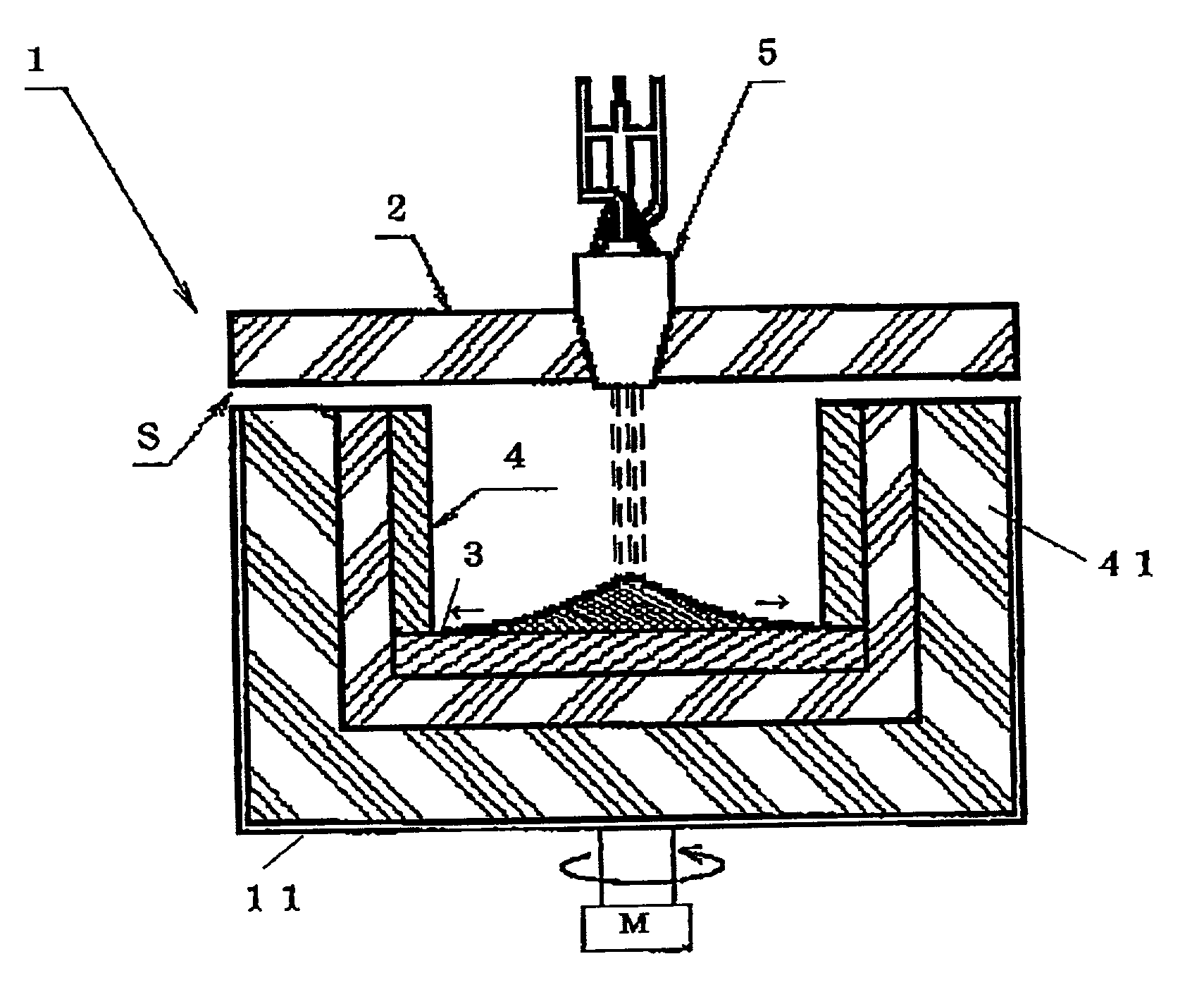
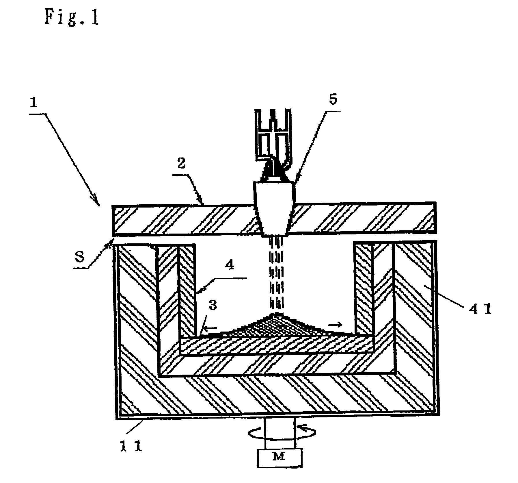
[0073] As shown in FIG. 1, A furnace 1 is placed on a rotatable frame 11 on which aluminum bricks are arrayed and a sidewalls 4 are erected with carbon silicate bricks conforming to a shape of the manufacturing quartz glass ingot. Outside the sidewalls 4, aluminum porous bricks and aluminum bricks are placed double forming a double wall 41 for heat insulation. A top of the furnace is open to tie air and a ceilin...

embodiment 2

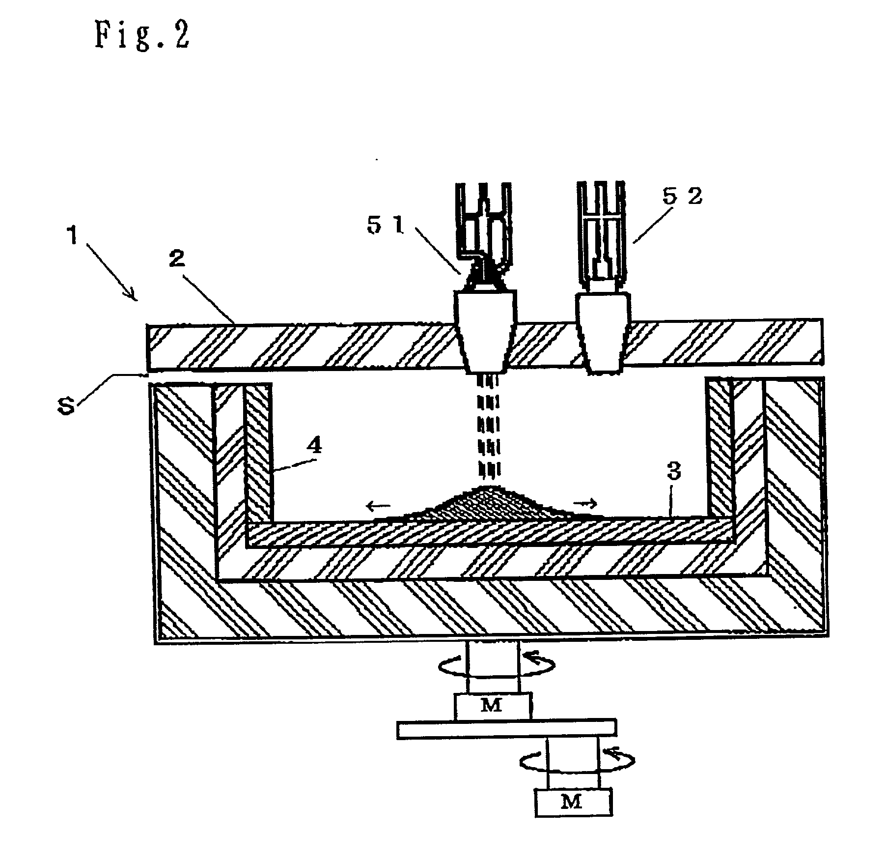
[0099] As shown in FIG. 3 and FIG. 4, a main burner 51 and a sub burner 52 (not shown) are installed in openings disposed in the ceiling 2, and hydrogen and oxygen supply pipes are connected to the burners. Silica powder is supplied from the silica hopper (not shown)through the silica supply pipe. A vibrating apparatus is attached to the silica powder supply system for preventing the stuck.

[0100] The furnace ceiling 2 and the furnace bed 3 consist of zirconia bricks and side wall is a double wall Construction consisting of zirconia bricks and aluminum bricks. A tungsten nozzle 6 is installed projecting to the inner furnace at the furnace bed 3, and under the nozzle 6, a .PHI. 100 mm opening is disposed, a diameter of the nozzle is adjusted to form a product diameter 41 mm. A 5 mm thick quartz glass plate 7 is placed upon the nozzle 6 for closing the nozzle hole.

[0101] Igniting the main burner 51 and the sub burner 52, preheating the furnace for 1 to 2 hours, then starting a supply o...

embodiment 3

[0105] As shown in FIG. 6, a plane view of the furnace 1, the size of the tungsten nozzle 6 is 220 (mm).times.8 (mm), section area of the furnace is 460 mm.times.230 mm, the coolant gas is hydrogen, and the furnace and the lif is not rotated and other conditions are same as the embodiment 3

[0106] With the supply of 320 Kg silica powder, 0.200 mm.times.7 mm section quartz glass plate of 102 m long and 292 Kg weight is obtained for 255 hours operation.

[0107] The deviation of the thickness and side length of the quartz glass plate product is within 1 mm per 1000 mm withdrawal of the product.


PUM

PropertyMeasurementUnit
diameteraaaaaaaaaa
diameteraaaaaaaaaa
thickaaaaaaaaaa

Abstract

The invention provides a method for manufacturing quartz glass large scale slab ingot in a flame hydrolysis reaction in a furnace, including the steps of rotating the furnace, depositing a fused silica on a furnace bed, and extending the deposit outwardly by heating and rotation of the furnace, thereby a quartz glass slab ingot is obtained. A quartz glass burner is installed at the ceiling of the furnace, hydrogen gas supplied to the burner is flowing down along the tapered wall of the oxygen chamber and being ejected into the outer casing part of the hydrogen gas is deflected to the center of the burner, and mixed with the oxygen just after the ejecton from the oxygen gas nozzles thereby the flame is formed smoothly and the thermal efficiency is improved, The flame becomes wide enough and the silica powder transported by the hydrogen gas is uniformly fused by the flame and heat capacity of the fused silica.

Description

[0001] 1. Field of the Invention[0002] The present invention relates to a method for manufacturing a quartz glass ingot, especially for manufacturing a quartz glass slab ingot, and further relates to a method for manufacturing a round bar or aplate quartz glass ingot containing OH, which is useful as a material for semi conductor manufacturing equipment[0003] Further the present invention relates to a quartz glass burner installed in a quartz glass manufacturing apparatus.[0004] 2. Prior Arts[0005] There are many methods for manufacturing a quartz glass ingot by fusing silica powder, in which the heat is supplied by a flame of hydrogen-oxygen or a flame of propane-oxygen, an arc, or by an electric heat. In general, as shown in Japanese patent Sho46-42111 (1971-42111, B2, JP), a quartz glass ingot is manufactured by fusing silica powder, depositing the fused silica on a rotating target, lowering the target gradually at a constant speed, and quenching the fused silica thereby forming ...

Claims


Application Information

Patent Timeline
Patent Type & Authority Applications(United States)
IPC IPC(8): C03B17/04C03B20/00C03B17/06C03B19/01C03B19/09C03B19/14F23D14/22F23D14/32
CPCC03B17/04C03B17/06C03B19/01C03B19/09C03B19/1407C03B19/1423C03B2207/06C03B2207/12C03B2207/14C03B2207/42C03B2207/54F23C2900/9901F23D14/22F23D14/32Y02E20/344
Inventor GOTOH, YOSHIHIKOSATOH, SHINICHIKUDOH, MASAKAZU
Owner TOSOH QUARTZ
Learn More