Optical device and fabrication thereof
a technology of optical devices and optical isolators, which is applied in the direction of laser optical resonator construction, laser details, semiconductor lasers, etc., can solve the problems of reducing performance and range, complex and costly, if not impossible, and complicating the procedures for reducing reflection back into the laser section, so as to achieve low internal reflex and good coupling efficiency
- Summary
- Abstract
- Description
- Claims
- Application Information
AI Technical Summary
Benefits of technology
Problems solved by technology
Method used
Image
Examples
first embodiment
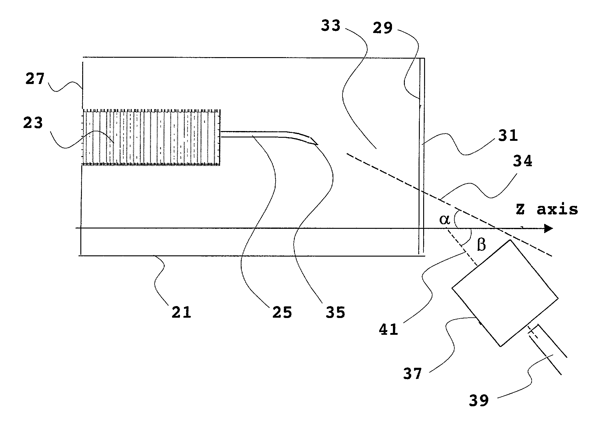
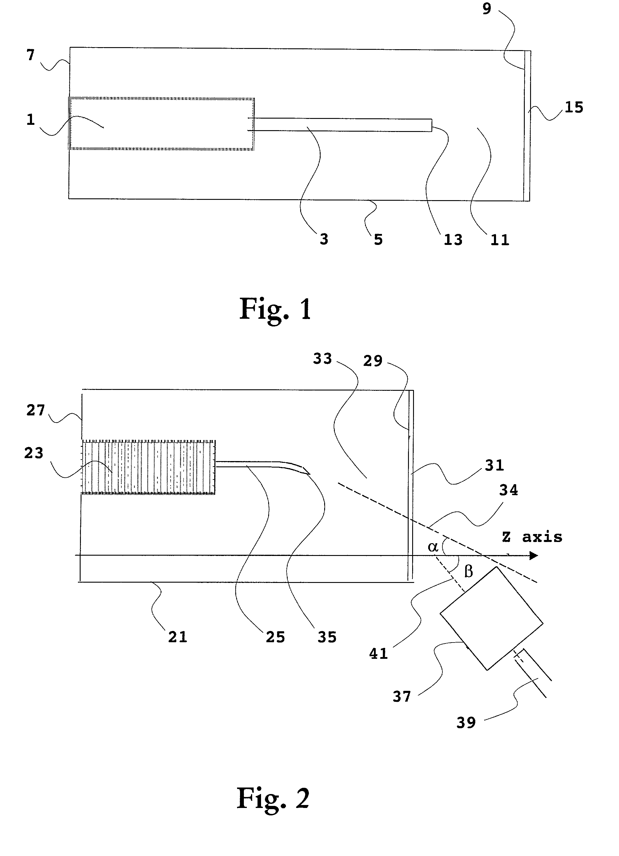
[0034] With reference to FIG. 2, which schematically illustrates a top view of an integrated laser / modulator device, the present invention will be depicted.
[0035] The integrated laser / modulator device comprises a substrate 21, in which a laser section 23 and a modulator section 25 are formed. The laser 23 is typically some kind of DFB (distributed feedback) laser, but may be any kind of suitable laser, e.g. a DBR (distributed Bragg reflection) laser. The modulator 25 is preferably an EAM (electro-absorption modulator), in which the waveguide has a bulk or a quantum well structure and the waveguide may be a buried or a ridge waveguide. Alternatively, the modulator is of other kind such as e.g. a Mach-Zehnder modulator.
[0036] The device is preferably fabricated in the material system InP / In.sub.1-xGa.sub.xAs.sub.yP.sub.1-y, but other material systems may be used.
[0037] Further, the device comprises a back facet 27 and a front facet 29 opposite to each other. Preferably, both facets ar...
second embodiment
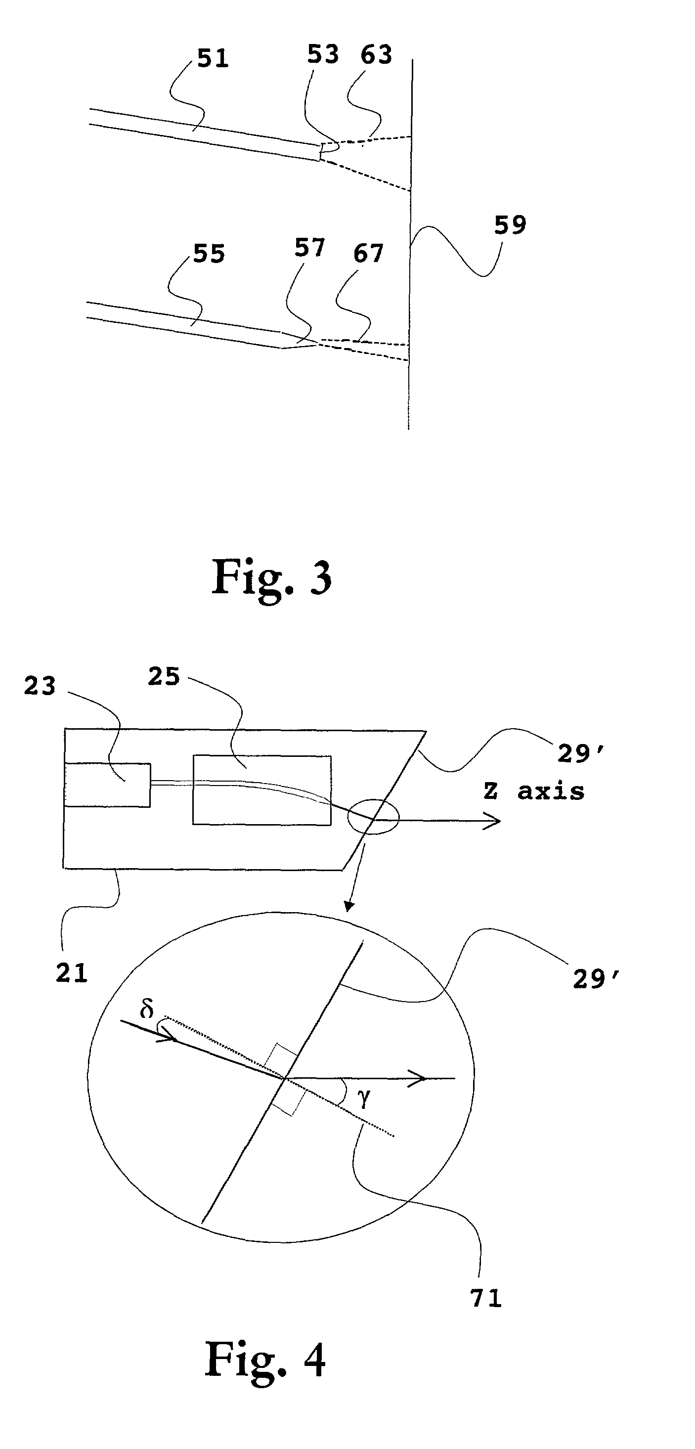
[0046] Next, with reference to FIG. 4, which is a schematic top view of an integrated laser / modulator device, wherein an enlargement of the front facet is shown in inset, the present invention will be depicted.
[0047] The device of this second embodiment is identical with the embodiment of FIG. 2 except that the device front facet, in FIG. 4 denoted 29', is angled with respect to the Z axis instead of positioning any external out-coupling device at an angle with respect to the Z axis. All other parts of the device have the same reference numerals as they have in FIG. 1. Also in this embodiment an AR coating (not illustrated) may cover the front facet.
[0048] The front facet 29' may be angled with respect to the Z axis by using any suitable technique such as e.g. dry etching. The angle .gamma. of the dry-etched window termination is essentially given by Snell's law (to give an output coupling parallel with the Z axis).
[0049] It shall particularly be noted that in this embodiment one pr...
PUM
 Abstract
Description
Claims
Application Information
 - R&D
- Intellectual Property
- Life Sciences
- Materials
- Tech Scout
- Unparalleled Data Quality
- Higher Quality Content
- 60% Fewer Hallucinations
Browse by: Latest US Patents, China's latest patents, Technical Efficacy Thesaurus, Application Domain, Technology Topic, Popular Technical Reports.
© 2025 PatSnap. All rights reserved.Legal|Privacy policy|Modern Slavery Act Transparency Statement|Sitemap|About US| Contact US: help@patsnap.com


