Electromagnetic wave shielding material

a shielding material and electromagnetic technology, applied in the field of electromagnetic shielding materials, can solve the problems of difficult cutting, poor thickness direction accuracy, difficult to obtain thin slices, etc., and achieve the effect of eliminating complicated processing steps and allowing more degree of freedom in design

Inactive Publication Date: 2002-02-07
SEIREN CO LTD
View PDF6 Cites 24 Cited by
  • Summary
  • Abstract
  • Description
  • Claims
  • Application Information

AI Technical Summary

Benefits of technology

0011] In JP-A 2001-3264, there is disclosed a knitted-woven fabric having a three dimensional structure with continuous holes, in which structure metal is attached to at least a portion of the structure thread and at least a portion of the structure thread is a conductive fiber. The publication states that the structure as described above allows a more degree of freedom in designing, enables obtaining three-dimensional structures of various sizes, and eliminates the complicated processing steps.

Problems solved by technology

However, in the aforementioned methods in which the elastic foam strap-like structure (such as a sponge) is employed, there arises a problem that slicing is difficult to perform when extremely thin slices (e.g., no thicker than 2 mm) are to be obtained, because slices are produced by slicing the sponge-like, elastic foam block by a predetermined thickness by a slicer, as described above.
As a result, in the case of the conventional method in which the strap-like structures are made by slicing, there may arise problems that thin slices are difficult to be obtained and the accuracy of dimension in the thickness direction is poor.
In addition, this conventional method ends up with a high production cost because it requires a number of production steps, such as compressing the slices under an increased pressure.
However, when a gasket is produced in such a manner, setting of the processing conditions (including selection of the raw material for effecting foaming, the charging and foaming method, the temperature condition) is difficult and thus high-standard control technique is required, resulting in a high facility cost, although the production efficiency thereof is relatively high.
Further, in the gasket of such a type, the dimension accuracy may be relatively poor because foaming tends to proceed to some extent even after the foamed product is pulled out of the mold.
However, as the conductive woven / unwoven cloth made of only the conductive material exhibits poor cushioning property, the conductive woven / unwoven cloth of such a type is not suitable as a gasket material.

Method used


Image

  • Electromagnetic wave shielding material
  • Electromagnetic wave shielding material
  • Electromagnetic wave shielding material

Examples


example 1

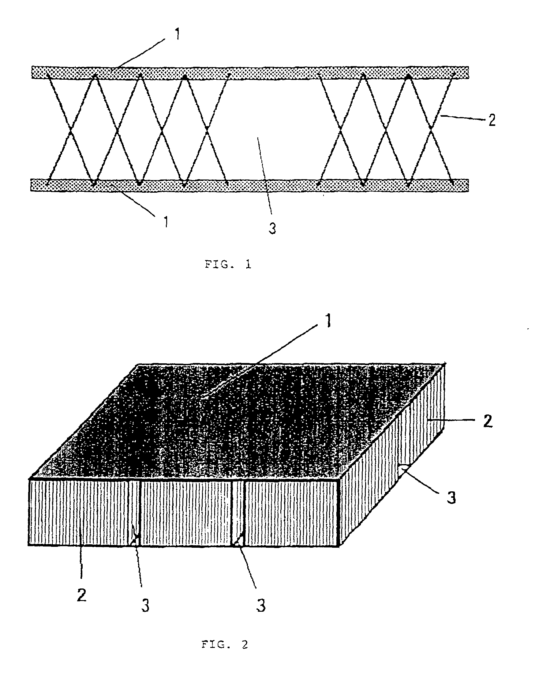
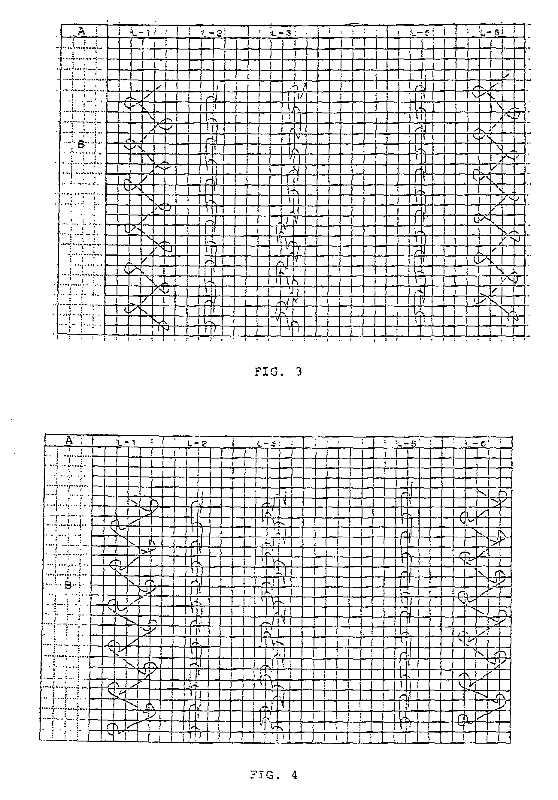
[0065] A double raschel three dimensionally knitted structure was produced by using the structure pattern as shown in FIG. 4 and a double raschel knitting device having 22 gauge. Polyester fiber of 33 dtex / 12 f was used as the ground structure. Monofilament made of polyester fiber of 22 dtex was used as the connection thread. A blank product of 24 course / inch and 22 well / inch was obtained. Next, the obtained blank product was scoured and dried, whereby excess oil contents and impurities were removed. Thereafter, the blank product was immersed, for two minutes, in an aqueous solution at the temperature of 40.degree. C. which contained 0.3 g / L of palladium chloride, 30 g / L of tin (I) chloride, and 300 ml / L of 36% hydrochloric acid. The blank product was then washed with water. Thereafter, the blank product was immersed, for five minutes, in borofluoric acid whose acid concentration was 0.1 N at the temperature of 30.degree. C. The blank product was then washed with water. Next, the bl...

example 2

[0066] A double raschel three dimensionally knitted structure was produced by using the same structure pattern as example 1 and a double raschel knitting device having 22 gauge. Polyester fiber of 33 dtex / 12 f was used at L1 and L6 of the ground structure. Polyester-based heat-fusing composite thread of 33 dtex / 12 f (the ratio of the core thereof made of regular polyester with respect to the sheath thereof made of low-melting point polyester being 1:1) was used at L2 and L5 of the ground structure. Monofilament made of polyester fiber of 22 dtex was used as the connection thread. A blank product of 24 course / inch and 22 well / inch was thus obtained. The weight percentage of the heat-fusing thread used in the product was 65.4%.

[0067] Next, the obtained blank product was scoured and dried, whereby excess oil contents and impurities were removed. Thereafter, the blank product was immersed, for two minutes, in an aqueous solution at the temperature of 40.degree. C. which contained 0.3 g / ...

example 3

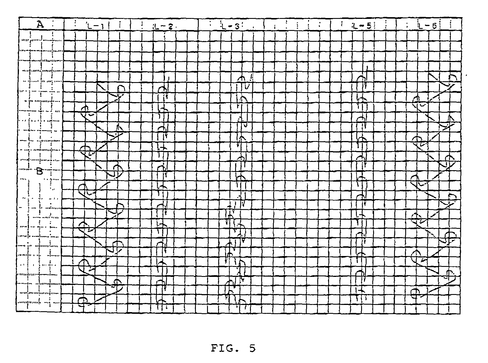
[0068] A double raschel three dimensionally knitted structure was produced by using the pattern structure as shown in FIG. 5 and a double raschel knitting device having 22 gauge. Polyester fiber of 33 dtex / 12 f was used at L1 and L6 of the ground structure. Polyester-based heat-fusing composite thread of 33 dtex / 12 f (the ratio of the core thereof made of regular polyester with respect to the sheath thereof made of low-melting point polyester being 1:1) was used at L2 and L5 of the ground structure. Monofilament made of polyester fiber of 22 dtex was used as the connection thread. A blank product of 24 course / inch and 22 well / inch was thus obtained. The percentage of the heat-fusing thread used in the product was 65.4%.

[0069] Next, the product was processed in a manner similar to that of example 2, whereby an electromagnetic wave shielding material was obtained. Cutting of the electromagnetic wave shielding material was carried out at the portion not having the connection thread. Th...


PUM

PropertyMeasurementUnit
thicknessaaaaaaaaaa
thicknessaaaaaaaaaa
thicknessaaaaaaaaaa

Abstract

The present invention provides an electromagnetic wave shielding material including a three dimensionally knitted base material and a conductive metal layer formed on the three dimensionally knitted base material, which shielding material is characterized in that it comprises: a heat-fusing thread used at at least a portion of the three dimensionally knitted base material; and a portion in which connection thread is not present, wherein the amount of cutting debris generated at the time of cutting is decreased. According to the present invention, an electromagnetic wave shielding material, which is used for an electromagnetic wave shielding gasket for shielding electromagnetic wave, exhibits good workability if the thickness of the product is relatively thin, suppresses the metal separation and reduces the amount of cutting debris generated at the time of cutting, is obtained.

Description

[0001] The present invention relates to an electromagnetic wave shielding material which shields undesirable electromagnetic wave radiated from outside of the environment and also shields electromagnetic wave leaking from Inside of the environment.[0002] In intelligent buildings and FA factories, electronic appliances and communication devices such as personal computers, office-automation devices, factory-automation devices etc have been generally introduced. As a result, erroneous operations of electronic devices, as well as electronic wave disturbance such as communication disturbance, which occur inside these buildings and factories due to the electromagnetic wave radiated from the electronic appliances and the communication devices as described above or undesirable electromagnetic wave coming from the outside of the environment, have now become a significant social problem.[0003] In order to prevent such leakage of undesirable electromagnetic wave from the environment, as well a...

Claims


Application Information

Patent Timeline
Patent Type & Authority Applications(United States)
IPC IPC(8): D04B21/04
CPCD10B2401/16D04B21/16D10B2403/021D10B2403/0112D10B2505/06D10B2401/041Y10T442/30Y10T428/23914Y10T442/444Y10T442/419Y10T442/438Y10T442/431Y10T442/40Y10T442/475Y10T442/481Y10T442/425Y10T442/3195
Inventor ORITA, SHIGEKAZUTAKEGAWA, TORUKATSUKI, YASUFUMISHIRASAKI, FUMIO
Owner SEIREN CO LTD
Why Eureka
Try Eureka