High current low resistance double latching battery switch

a battery switch, low resistance technology, applied in the field of switches, can solve the problems of constant drain on the battery, increase the complexity and cost of these systems, and maintain the battery for a long time, and achieve the effect of low resistan

Inactive Publication Date: 2002-03-14
JOHNSON CONTROLS TECH CO
View PDF0 Cites 41 Cited by
  • Summary
  • Abstract
  • Description
  • Claims
  • Application Information

AI Technical Summary

Benefits of technology

0019] It is therefore an advantage of the present invention to provide an anti-theft battery switch that provides a single circuit path between the battery and the vehicle starter and accessories.
0020] It is another advantage of the present invention to provide an anti-theft battery switch that can be latched into an open or closed position without the need for a continuous supply of electric current from the battery.
0021] It is still another advantage of the present invention to provide an anti-theft battery switch that has a low resist...

Problems solved by technology

While the aforementioned anti-theft batteries can provide certain protection against vehicle theft, these batteries do have drawbacks.
It is believed that these dual circuit paths used in known anti-theft batteries add to the complexity and cost of these systems.
This can be a disadvantage in that a constant drain is kept on the battery.
The battery manufacturer is then faced with the dilemma of either redesigning the anti-theft battery to increase cold cranking ratings or dropp...

Method used


Image

  • High current low resistance double latching battery switch
  • High current low resistance double latching battery switch
  • High current low resistance double latching battery switch

Examples


example 1b

Switch Contact Resistance Measurement

[0063] A current of 600 amps was then passed through the twenty-eight switch assemblies as described in Example 1A and the voltage drop measured across the contacts was then divided by 600 (i.e., 600 amps) to determine the resistance between the contacts. The average resistance for the twenty-eight switch assemblies between contacts was 0.15.+-.0.025 milliohms.

example 2

Battery Cold Cranking Test Simulation

[0064] Six switch assemblies in accordance with the present invention were constructed. The switch assemblies were placed in an 0.degree. F. (-18.degree. C.) environment for at least 6 hours. A current of 900 amps was then passed for 45 seconds through the switch assemblies as in Examples 1A and 1B. The voltage drop across the first and second contacts was then measured. The voltage drop across the contacts was then divided by 900 (i.e., 900 amps) to determine the resistance between the contacts. The same 900 amp current was then passed for 45 seconds through the switch assemblies for a second time. The results of the twelve tests showed a resistance between contacts ranging from 0.102 milliohms to 0.139 milliohms.

example 3

Temperature Resistance of the Buss Bar of the Relay

[0065] A computer simulation was performed to determine the mass of the relay buss bar according to the invention that will provide acceptable performance under the high currents present during vehicle starting. It was determined that a relay buss bar temperature in excess of 100.degree. C. was unacceptable during vehicle starting as the buss bar could experience physical damage under the high temperatures.

[0066] The projected temperature rise for different masses of copper alloy (CDA 110) relay buss bars was calculated using a simulated cold crank test having current and duration values of 800 amps for 45 seconds. These values were selected to fall within the range of cold cranking amps expected from a premium vehicle battery as detailed in the Background of the Invention section above. It was discovered that a relay buss bar mass of about 5 grams is required in order to keep the temperature of the relay buss bar at or below 100.de...


PUM


Abstract

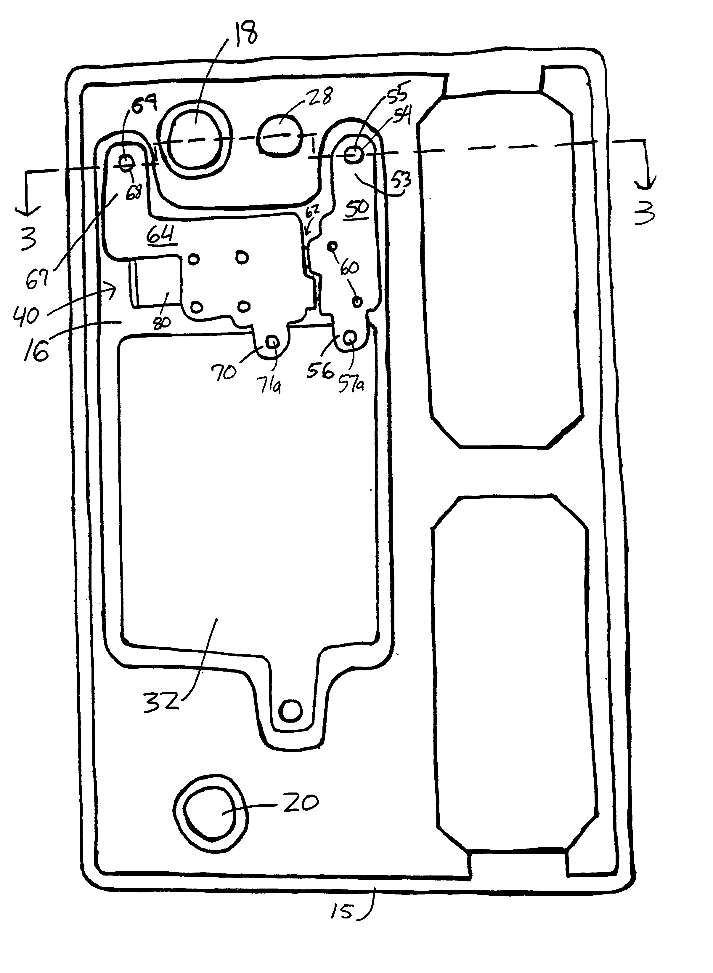
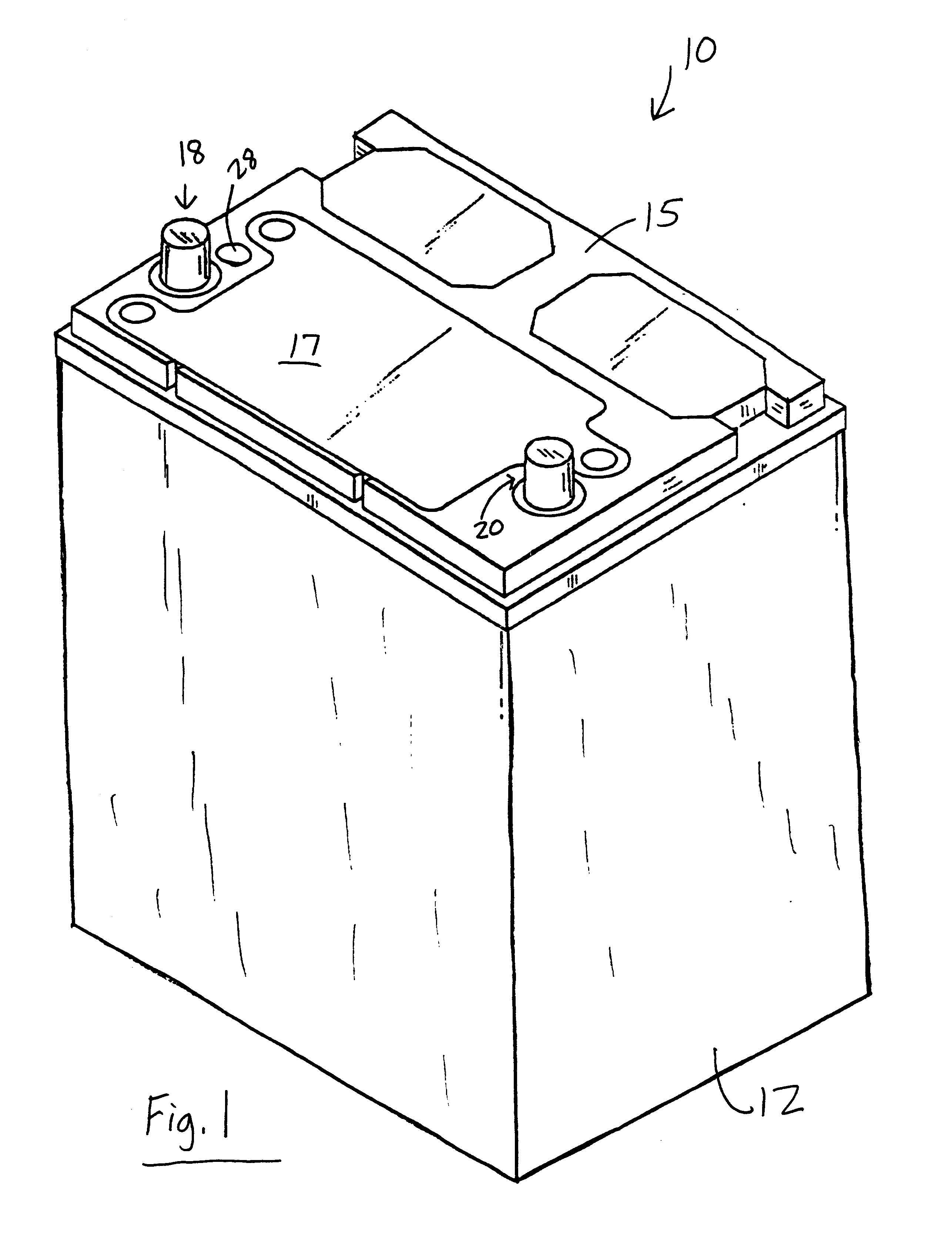
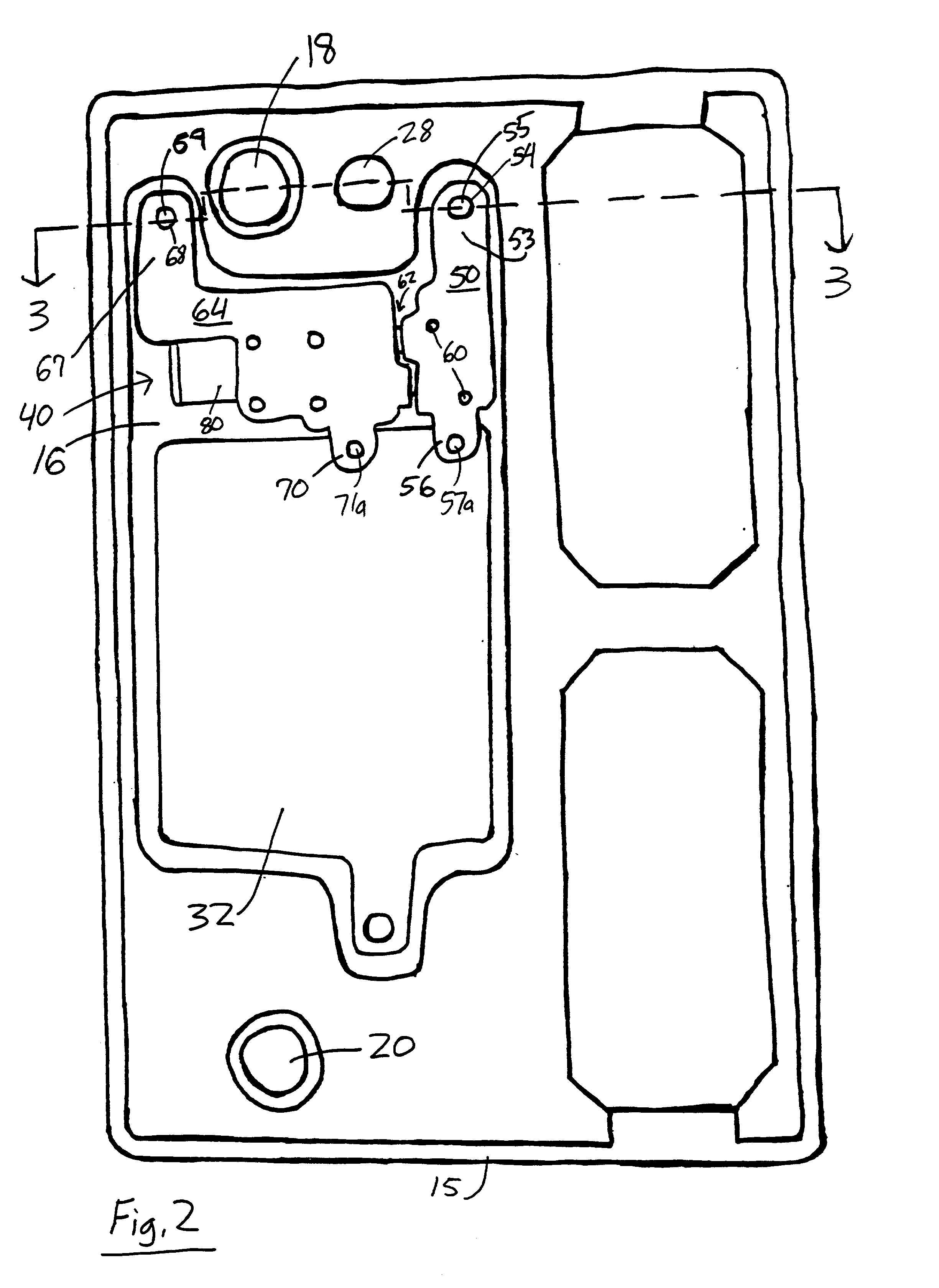
A switch for controlling the supply of current from a battery cell in a cell cavity to a battery terminal in a battery casing is disclosed. The switch includes a mounting base, a first buss bar connected to the mounting base and connectable to the battery cell, a second buss bar connected to the mounting base and connectable to the battery terminal, and a relay having open and closed positions. The relay includes a third buss bar that places the first buss bar and the second buss bar in contact to provide current from the battery cell to the battery terminal when the relay is in the closed position. The relay is moved into a latched open position when a first winding of a coil of the relay is energized by electricity, and is moved back into a latched closed position when a second winding of the coil is energized.

Description

[0001] This application claims the benefit of U.S. Provisional Patent Application No. 60 / 222,524 filed Aug. 2, 2000.[0002] 1. Field of the Invention[0003] This invention relates to switches for controlling a supply of electric current from a battery cell in a battery cell cavity to a battery terminal in a battery casing, and more particularly to a high current, low resistance latching anti-theft battery switch for use in vehicle batteries.[0004] 2. Description of the Related Art[0005] Motor vehicles typically include a lead-acid storage battery to power an electric starter motor and to run vehicle accessories, such as lights, clocks, and radios. When choosing a correct battery for a motor vehicle, an automotive engineer generally looks at the ability of a battery to power the starter to enable minimum starting speed under very cold conditions. As a result, various accepted performance ratings have been developed for automotive batteries so that a person choosing a battery can match ...

Claims


Application Information

Patent Timeline
IPC IPC(8): H01M10/42H01M50/296H01M50/541H01M50/55H01M50/583
CPCH01M2/28H01M2/305H01M2/34H01M2/341H01M10/425Y02E60/10H01M50/541H01M50/576H01M50/583H01M50/55H01M50/296
Inventor WRUCK, WILLIAM J.TAGHIKHANI, MAJIDKAO, WEN-HONGMROTEK, EDWARD N.THOMPOSON, MICHAEL L.PFEIFER, GUY L.BERRY, WILLIAMRAJNOVIC, NICKKRENZ, JAMES R.NYKIEL, DENNIS
Owner JOHNSON CONTROLS TECH CO
Why Eureka
Try Eureka