
Ink for producing membrane electrode assemblies for fuel cells

a fuel cell and membrane electrode technology, applied in the direction of fuel cells, electrochemical generators, electrical equipment, etc., can solve the problems of unsatisfactory so-called "screen life" during which screen printing is possible, affecting the production efficiency of fuel cells, and requiring a very long activation and conditioning period before acceptable electrical performance, etc., to achieve long screen life and high production safety

Inactive Publication Date: 2002-03-21
DMC2 DEGUSSA METALS CATALYSTS CERDEC +1
View PDF16 Cites 40 Cited by
  • Summary
  • Abstract
  • Description
  • Claims
  • Application Information

AI Technical Summary

Benefits of technology

[0018] It has been shown that an ink which contains substantially water as solvent has surprisingly good adhesion to the polymer membrane when it contains, as additional solvent, 1 to 50 wt. %, preferably 5 to 25 wt. %, (with respect to the water content of the ink) of a compound from the group of linear dialcohols with flash points higher than 100.degree. C. In addition, these inks have a very good screen life with regard to screen printing and good electrical performance values in the PEM fuel cell. Obviously, linear dialcohols have the effect of bringing about intimate contact between the catalyst layer and the ionomer membrane and thus producing good adhesion and electrical performance.
[0020] Thus, high production safety is achieved when processing these inks. In addition, a long screen life is enabled during use in screen printing processes and this clearly exceeds that of pure water-based pastes (according to EP 0 731 520 A1).

Problems solved by technology

In addition, it has been shown that the ink can be processed only over a very short time by means of a screen printing process due to the low boiling point of isopropanol; the so-called "screen life" during which screen printing is possible is unsatisfactory.
Furthermore, the glycerine present in the ink means that the membrane electrode assembly (MEA) requires a very long activation and conditioning period before acceptable electrical performance is obtained.
Due to the high proportion of solvent, they tend to ignite.
The considerable emissions of organic compounds (solvents are "volatile organic compounds"=VOCs) is a problem with regard to occupational health and safety and the protection of the environment, in particular when mass producing components for fuel cells.
This ink is therefore unsuitable for the electrodes and MEAs which are used in PEM fuel cells.
When the applicants checked this ink, it was shown that it led to electrode layers which adhered too poorly to the polymer membrane.
As a result, the electrical performance of MEAs produced with this ink is inadequate.
Likewise, when screen printing with this ink, it was shown that it thickened very rapidly and thus had inadequate screen lifes for screen printing.

Method used


Image

  • Ink for producing membrane electrode assemblies for fuel cells

Examples


example 1

[0038] Differently from comparison example 1, the amount of water was reduced to 27 g and replaced by 8 g of dipropylene glycol in accordance with the invention:

3 15.0 g Pt supported catalyst (40% Pt / C, dmc.sup.2) 50.0 g Nafion .RTM. solution (10% in water) 27.0 g water (fully deionized) 8.0 g dipropylene glycol 100.0 g

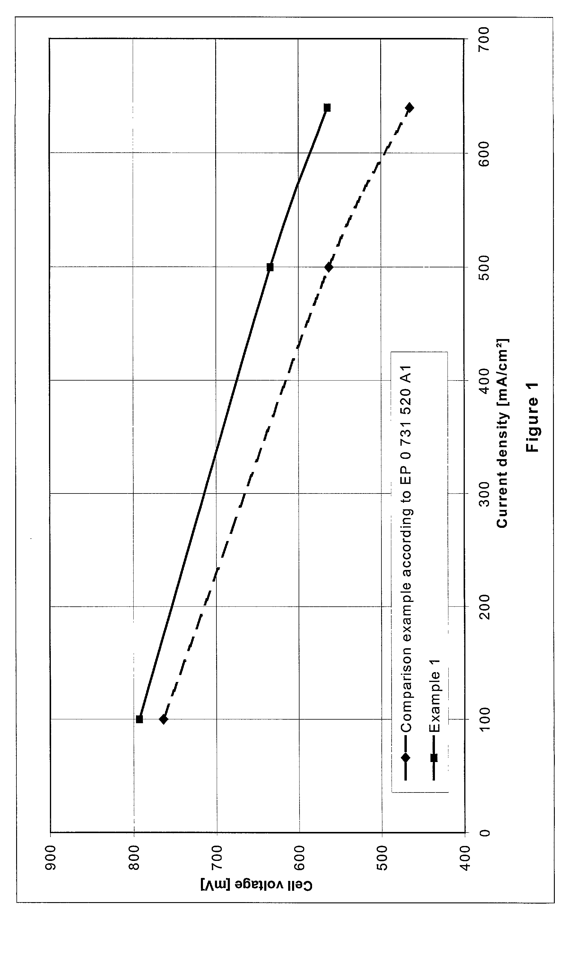
[0039] The ratio by weight of catalyst to Nafion.RTM. was 3:1. The proportion of dipropylene glycol was 11 wt. % (with respect to the total water content). The ink was applied to the anode and cathode sides of the ionomer membrane Nafion.RTM. 112 as described in comparison example 1. Adhesion of the electrode layers to the membrane after drying and humidifying with water was very good, no peeling of the layers was observed. The total Pt loading was 0.6 mg Pt / cm.sup.2. The MEA produced in this way was measured in the PEM single cell test. At a current density of 500 mA / cm.sup.2 a cell voltage of 634 mV was measured. This value was about 70 mV above the cell voltage in ...

example 2

[0040] The following components were homogenized:

4 15.0 g PtRu supported catalyst (40% PtRu / C: 26.4% Pt, 13.6% Ru; catalyst according to US 6,007,934) 60.0 g Nafion .RTM. solution (10% in water) 15.0 g water (fully deionized) 10.0 g ethylene glycol 100.0 g

[0041] The ratio by weight of catalyst to Nafion.RTM. was 2.5:1. The proportion of ethylene glycol was 14.5 wt. % (with respect to the total water content). The ink was applied to the anode side of an ionomer membrane (Nafion.RTM. 112, DuPont) and then dried at 80.degree. C. Then the ink according to the invention from example 1 was applied to the rear side of the membrane (cathode side) and again dried. After drying, the MEA was moistened with water and then placed moist between two gas distributor substrates. Adhesion of the catalyst layers to the membrane was very good. Measurements were performed in the PEM single cell operating with hydrogen / air. At 500 mA / cm.sup.2 a cell voltage of 620 mV was measured. The MEA also had very g...

example 3

[0042] Another ink was prepared, with the following composition:

5 15.0 g Pt supported catalyst (40% Pt / C, dmc.sup.2) 50.0 g Nafion .RTM. solution (10% in water) 20.0 g water (fully deionized) 15.0 g diethylene glycol 100.0 g

[0043] The ratio of catalyst to Nafion.RTM. was 3:1. The proportion of diethylene glycol was 23 wt. % (with respect to total water content). The ink was applied to the front and rear sides of an ionomer membrane (thickness 30 .mu.m). Adhesion of the catalyst layers after drying and humidification with water was very good. The performance in a PEM single cell operating with hydrogen / air was 650 mV with a current density of 500 mA / cm.sup.2.


PUM


Abstract

An ink is disclosed for producing membrane electrode assemblies for fuel cells which contains a catalyst material, an ionomer, water and an organic solvent. The ink is characterized in that the organic solvent is at least one compound from the group of linear dialcohols with a flash point higher than 100° C. and is present in the ink in a concentration between 1 and 50 wt. %, with respect to the weight of water.

Description

INTRODUCTION AND BACKGROUND[0001] The present invention relates to an ink for producing membrane electrode assemblies for fuel cells, in particular for polymer electrolyte membrane fuel cells (PEM fuel cells) and direct methanol fuel cells (DMFC). More particularly, the present invention relates to a water-based catalyst ink for producing membranes coated with catalyst, electrodes and membrane electrode assemblies (MEAs).[0002] Fuel cells convert a fuel and an oxidising agent which are spatially separated from each other at two electrodes into electricity, heat and water. Hydrogen or a hydrogen-rich gas may be used as the fuel and oxygen or air as the oxidizing agent. The process of energy conversion in the fuel cell is characterised by particularly high efficiency. For this reason, fuel cells in combination with electric motors are becoming more and more important as an alternative to traditional internal combustion engines. The PEM fuel cell is suitable for use as an energy conver...

Claims


Application Information

Patent Timeline
IPC IPC(8): H01M4/88H01M4/92H01M8/1004
CPCH01M4/881H01M4/8828H01M4/926H01M8/1004Y02E60/521Y02P70/50Y02E60/50H01M8/02
Inventor STARZ, KARL-ANTONZUBER, RALFKRAMER, ANITAFEHL, KNUTKOHLER, JOACHIMWITTPAHL, SANDRA
Owner DMC2 DEGUSSA METALS CATALYSTS CERDEC
Learn More