Filter, duplexer, and communication device
- Summary
- Abstract
- Description
- Claims
- Application Information
AI Technical Summary
Benefits of technology
Problems solved by technology
Method used
Image
Examples
first embodiment
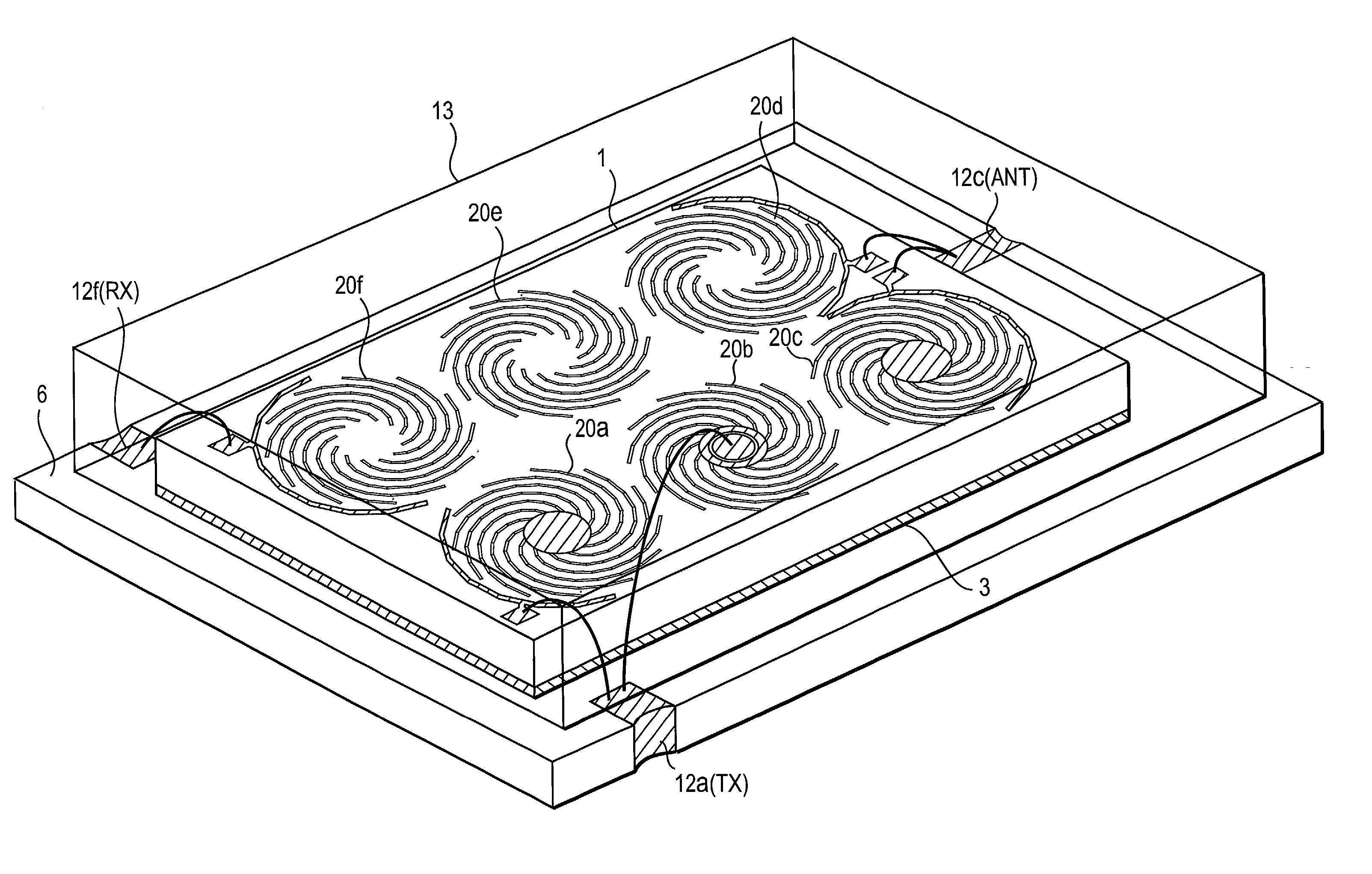
[0061] First, the configuration of a filter in accordance with the present invention will be described with reference to FIG. 5.
[0062] FIG. 5 is a perspective view showing the filter in its entirety. Here, the figure is drawn by seeing through a cap 13. In FIG. 5, reference numeral 1 denotes a high-permittivity substrate formed of LaNbO.sub.3, (Zr, Sn) TiO.sub.4, barium titanate-based material, or the like. By arranging three multiple spiral lines on the top surface of this substrate, three multiple spiral resonators are formed. At the outer periphery portions of the dispositional area of the two outermost multiple spiral lines among these three multiple spiral lines, outer periphery coupling electrodes 14a and 14c which create an electrostatic capacitance between the outer peripheral edges and these electrodes are each formed. On the top surface of the dielectric substrate 1, bonding pads 10a and 10c are also formed. A ground electrode 3 is formed over substantially the entire bott...
second embodiment
[0075] FIG. 6 is a perspective view showing a filter in accordance with the present invention. In this example, unlike the filter shown in FIG. 5, the first-stage resonator formed of the multiple spiral line 20a and the third-stage resonator formed of the multiple spiral line 20c are each set to be left-handed resonators, and the second-stage resonator formed of the multiple spiral line 20b is set to be a right-handed resonator. As shown in FIG. 15 and others, since the coupling between a left-handed resonator and a right-handed resonator is weaker than that between two left-handed resonators, the coupling between the adjacent resonators in the three stages shown in FIG. 6 is weak, which provides passing characteristics in a narrow bandwidth. In this connection, if all of the three resonators are set to be left-handed resonators, the spacings among these resonators must be increased in order to obtain a narrow pass band, which would result in an overall increase in the size of the f...
fourth embodiment
[0082] Next, a filter in accordance with the present invention will be described in reference to FIGS. 8 and 9.
[0083] FIG. 8 is a perspective view of this filter. Unlike the example shown in FIG. 7, a ring-shaped connection electrode 8b is connected to the inner peripheral edge of the multiple spiral line of the second-stage resonator. Inside this connection electrode 8b, there is further formed a coupling pad 9 for creating an electrostatic capacitance between the connection electrode 8b and this coupling pad 9. Also, circular connection electrodes 8a and 8c are connected to the inner peripheral edges of the multiple spiral lines of the first-stage and third-stage resonators.
[0084] FIG. 9 shows a comparison of the spurious response characteristics of the resonator, when the inner peripheral edges of the multiple spiral resonators are connected by the connection electrodes 8a, 8b and 8c, and when they are not connected. As can be seen from this figure, when the inner peripheral edge...
PUM
 Abstract
Description
Claims
Application Information
 - R&D
- Intellectual Property
- Life Sciences
- Materials
- Tech Scout
- Unparalleled Data Quality
- Higher Quality Content
- 60% Fewer Hallucinations
Browse by: Latest US Patents, China's latest patents, Technical Efficacy Thesaurus, Application Domain, Technology Topic, Popular Technical Reports.
© 2025 PatSnap. All rights reserved.Legal|Privacy policy|Modern Slavery Act Transparency Statement|Sitemap|About US| Contact US: help@patsnap.com


