
Compound having pyrrole ring and light-emitting device comprising same

a technology of pyrrole ring and light-emitting device, which is applied in the direction of solid-state devices, discharge tubes/lamp details, natural mineral layered products, etc., can solve the problems of insufficient light-emitting properties of light-emitting devices comprising polymerized triarylamine derivatives, poor solubility of triarylamine derivatives in organic solvents, and general poor durability of light-emitting devices using the derivatives. , to achiev

Inactive Publication Date: 2002-04-11
UDC IRELAND +1
View PDF0 Cites 27 Cited by
  • Summary
  • Abstract
  • Description
  • Claims
  • Application Information

AI Technical Summary

Benefits of technology

[0005] An object of the present invention is to provide a compound usable for a light-emitting device that can emit light with high luminance and excellent light-emitting efficiency, and a light-emitting device comprising the compound.
[0006] As a result of intense research in view of the above object, the inventor has found that a light-emitting device using a particular compound having a pyrrole ring emits light with high luminance and excellent light-emitting efficiency. The present invention has been accomplished by the finding.

Problems solved by technology

However, the triarylamine derivatives are generally high in crystallinity, whereby light-emitting devices using the derivatives are generally poor in durability during storage and driving.
Further, although the organic thin layers are desirably provided by a coating method from viewpoints of simplification of production processes, improvement of workability, increasing the light-emitting device in size, etc., the triarylamine derivatives is poor in solubility in an organic solvent to be not suitable for the coating method.
Additionally, the inventor has found that light-emitting devices comprising polymerized triarylamine derivatives exhibit insufficient light-emitting properties.
However, the light-emitting devices using such a hole-transporting material are poor in light-emitting efficiency and require high applying voltage for light emission.

Method used


Image

  • Compound having pyrrole ring and light-emitting device comprising same
  • Compound having pyrrole ring and light-emitting device comprising same
  • Compound having pyrrole ring and light-emitting device comprising same

Examples


examples 9 to 16

[0068] (b) Examples 9 to 16 and Comparative Examples 7 to 12

[0069] Light-emitting devices of Examples 9 to 16 and Comparative Examples 7 to 12 were produced in the same manner as production of the devices of Examples 1 to 8 and Comparative Examples 1 to 6 except for using Ir(ppy).sub.3 shown below, which utilizes a triplet exciton for light emission, in stead of coumarin-6, respectively. 8

[0070] Each of thus-obtained light-emitting devices was made to emit light while applying direct current voltage thereto by "Source-Measure Unit 2400" manufactured by TOYO CORPORATION, and measured with respect to luminance by "Luminance Meter BM-8 " manufactured by TOPCON CORPORATION. The compound used for each light-emitting device, luminance obtained when a direct current voltage of 18 V was applied to each device, and the maximum luminance of each device were shown in Table 2.

2TABLE 2 Light-Emitting Luminance Maximum Luminance Device Compound (at 18 V, cd / m.sup.2) (cd / m.sup.2) Comp. Ex. 7 PVK 4...


PUM

PropertyMeasurementUnit
work functionaaaaaaaaaa
thicknessaaaaaaaaaa
thicknessaaaaaaaaaa

Abstract

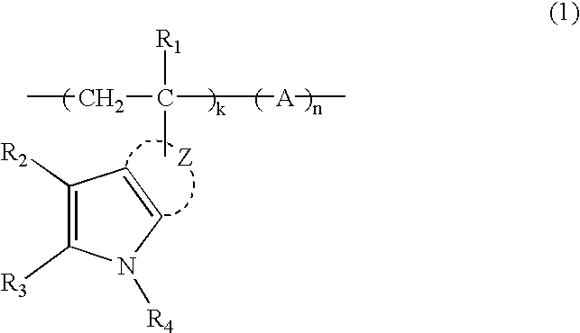
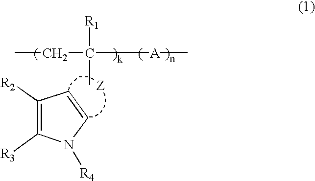
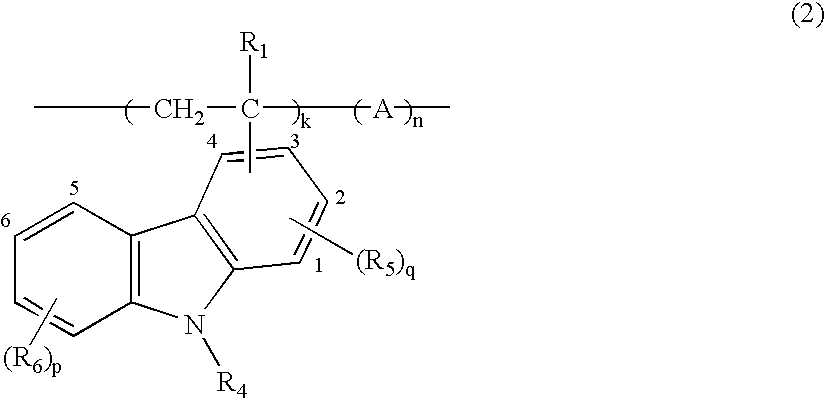
A compound represented by the following general formula (1) and a light-emitting device comprising the compound. In the general formula (1), R1 represents a hydrogen atom or a methyl group; R2 and R3 independently represent a hydrogen atom or a substituent and may bond together to form a ring; R4 represents a hydrogen atom or a substituent selected from the group consisting of alkyl groups, alkenyl groups, alkynyl groups, aryl groups, heterocyclic groups, alkylcarbonyl groups, arylcarbonyl groups, alkylsulfonyl groups, arylsulfonyl groups, alkoxycarbonyl groups, aryloxycarbonyl groups, carbamoyl groups and sulfamoyl groups; Z represents an atomic group forming an aromatic ring; A represents a comonomer unit; and k and n each represent a mole fraction, k being 1 to 100 (%), n being 0 to 99 (%), and the sum of k and n is 100 (%).

Description

[0001] The present invention relates to a compound having a pyrrole ring and a light-emitting device comprising the compound.[0002] Recently, various display devices have been widely studied. In particular, light-emitting devices including organic EL devices are advantageous in that they can emit light with high luminance by lowered applying voltage, whereby much attention has been paid thereto.[0003] For example, a light-emitting device comprising organic thin layers, which are provided by vapor-depositing organic compounds, has been disclosed in Applied Physics Letters, 51, 913 (1987). This light-emitting device has a structure where an electron-transporting layer and a hole-transporting layer are laminated between electrodes, to exhibit more excellent light-emitting properties than that of conventional devices having a single-layer structure. In this light-emitting device, N,N'-di-m-tolyl-N,N'-diphenylbenzidine (TPD) is used as a hole-transporting material for the hole-transporti...

Claims


Application Information

Patent Timeline
Patent Type & Authority Applications(United States)
IPC IPC(8): C08F26/00C09K11/06H10K99/00
CPCH01L51/004H01L51/0042Y10S428/917H01L51/0059H01L51/5012H01L51/0043H10K85/141H10K85/146H10K85/151H10K85/631H10K50/11
Inventor TAGUCHI, TOSHIKI
Owner UDC IRELAND
Learn More