Laser method for shaping of optical lenses

a laser method and optical lens technology, applied in the field of laser method, can solve the problems of not meeting the individual needs of a given patient, not being able to achieve optimal visual acuity, and custom ground lenses are prohibitively expensive for most patients

Inactive Publication Date: 2002-04-25
WESTAR PHOTONICS
View PDF0 Cites 15 Cited by
  • Summary
  • Abstract
  • Description
  • Claims
  • Application Information

AI Technical Summary

Problems solved by technology

Although correction factors for a patient can be determined with a great deal of accuracy and precision, commercial lenses are provided with standard corrections which do not necessarily fit a given patient's individuals needs.
Custom ground lenses are prohibitively expensive for most patients, as the process of custom grinding requires a highly...

Method used


Image

  • Laser method for shaping of optical lenses
  • Laser method for shaping of optical lenses
  • Laser method for shaping of optical lenses

Examples


Embodiment Construction

[0030] During the course of this description like numbers will be used to identify like elements according to the different views that illustrate the invention.

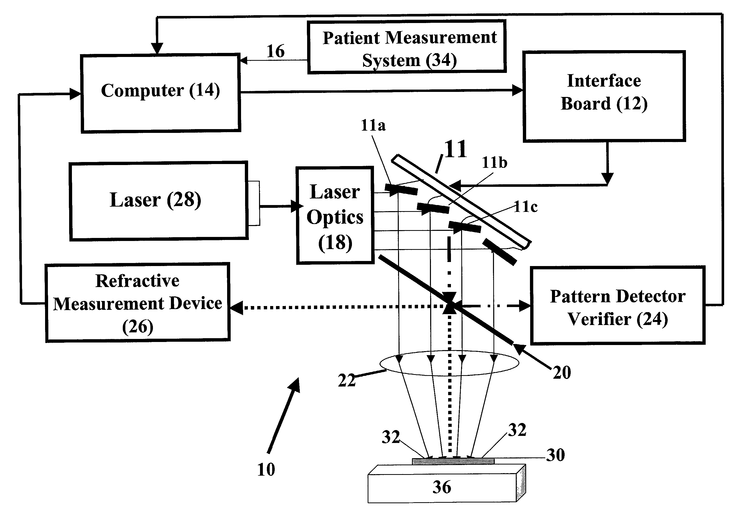
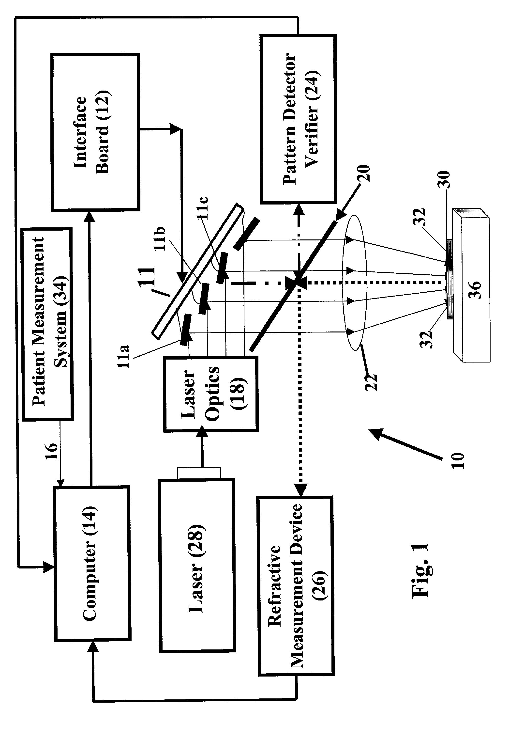
[0031] FIG. 1 shows a schematic diagram of a laser beam apparatus of use in a preferred embodiment of the method of the present invention. The apparatus includes a laser beam modifying system 11, an interface board 12, a computer 14, a computer input 16, laser optics 18, beam splitter 20, re-imaging optics 22, pattern detector and verifier 24, refractive measurement device 26, a laser 28, a index marks 34, a patient measurement system 34, and an XY table 36.

[0032] In the preferred embodiment of this invention, the laser modifying system 11 is a thin-film micromirror array as illustrated in FIG. 1. Thin-film micromirror 11 has a plurality of individual micromirrors 11a,b,c . . . , each of which can be individually tilted with respect to incident laser beamlets. In actual practice, a laser beam emanating from laser 28 is split ...


PUM


Abstract

A method for making accurate and precise customized corrections to the surface of an optical lens is described. An electronic correction contour is generated from a measured refractive correction for a patient, and transferred to the surface of the lens by ablation etching with one or more laser pulses. After each of the laser pulses, the refractive properties of the lens are measured and compared to the electronic contour correction derived from a patient's refractive correction. The ablation etching is terminated in localized areas where the refractive properties match the electronic correction contour. End point detection includes monitoring refractive qualities of the lens during the recontouring process, modifying the pattern through changes in the laser pulses.

Description

[0001] This application claims the priority of U.S. Provisional Application Ser. No. 60 / 224,647 entitled "A Laser Beam Patterning Device and Apparatus for Reshaping of Eyeglass Lenses by Ablation and Continuous Process Monitoring" filed on Aug. 8, 2000 the entire contents and substance of which are hereby incorporated in total by reference.[0002] 1. Field of the Invention[0003] This invention relates to a laser method for rapid and accurate shaping of optical lenses.[0004] 2. Description of Related Art[0005] The use of ablation etching to pattern polymeric material is well known in the art. In U.S. Pat. No. 4,508,749, for example, Brannon et al. discloses an ultraviolet radiation based method for etching patterns in polyimide layers located on integrated circuit substrates, and subsequently depositing an electrical circuit pattern thereover to form electrical interconnections to elements of the integrated circuit. In U.S. Pat. No. 5,236,551, Pan describes a laser-based photoablative...

Claims


Application Information

Patent Timeline
IPC IPC(8): A61F9/01B23K26/03B23K26/06B23K26/067B23K26/42
CPCA61F9/00804A61F9/00817A61F2009/00846A61F2009/00872B23K26/426B23K26/0608B23K26/0656B23K26/067B23K26/032B23K26/066B23K26/705
Inventor BRANDINGER, JAY J.HOFFMAN, BRIAN D.POLKOWSKI, EDWARD T.
Owner WESTAR PHOTONICS
Why Eureka
Try Eureka